Distributed optical fiber monitoring system for tunnel surrounding rock deformation and construction and monitoring methods thereof
A distributed optical fiber and surrounding rock deformation technology, which is applied in measurement devices, optical devices, instruments, etc., can solve the problems of tunnel surrounding rock advance deformation monitoring without a relatively complete monitoring system construction technology and monitoring methods, and achieve accurate reflection. Effect
- Summary
- Abstract
- Description
- Claims
- Application Information
AI Technical Summary
Problems solved by technology
Method used
Image
Examples
Embodiment 1
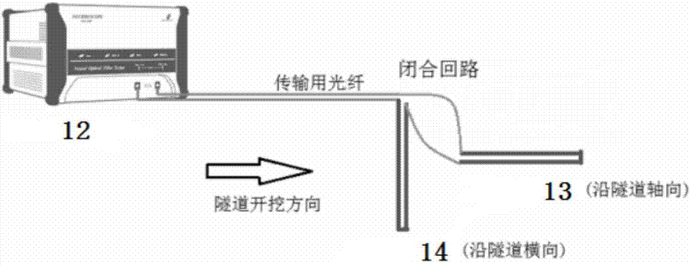
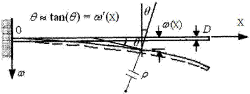
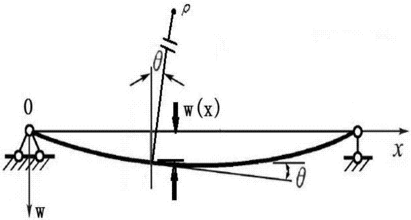
[0056] according to figure 1 , figure 2 , image 3 , Figure 4 , Figure 5 , Image 6 , Figure 7 , Figure 8 It can be seen that an advanced monitoring system for tunnel surrounding rock deformation based on PPP-BOTDA distributed optical fiber sensing consists of a first sensor 13 , a second sensor 14 and an information system 12 . The first sensor 13 and the second sensor 14 can be connected in series, and the first sensor 13 and the second sensor 14 are connected with the host computer interface of the information system 12 to form a closed loop. 1m×1m brick groove 3, inner connection pipe 4, right-angle elbow 5, first groove 6, second groove 7, third groove 8, fourth groove 9, heat shrinkable sleeve 10, vertical conduit 11 , the connection relationship is: the hollow tube 2 is connected to the inner tube, the hollow tube 2 is welded by the inner tube 4 to reach the expected length, and the optical fiber 1 is laid in the first groove 6 and the second groove 7 to for...
Embodiment 2
[0060] A construction method of a tunnel surrounding rock deformation advanced monitoring system (first sensor, second sensor) based on PPP-BOTDA distributed optical fiber sensing, the steps are:
[0061] A. Firstly, in the influence area of the cross section between the underpass tunnel and the existing structures and buildings such as existing roads, tunnels, and office buildings, along the axial direction of the tunnel (the second sensor 14 is along the tunnel cross-section direction of the cross section) on the ground surface Excavation of trenches, the trench length ranges from 5 or 6 or 7 or 8 meters to 500 or 600 or 700 or 800 meters (the length of the trench in the cross-sectional direction is 3 or 4 or 5 times the tunnel diameter from the horizontal distance of the tunnel axis), the trench The width is 0.5 or 0.7 or 0.9 or 1m, the depth of the trench can be determined as 0.5 or 0.8 or 1.5 or 2 or 2.4 or 2.8 or 3m according to the construction site conditions, and the...
Embodiment 3
[0071] A method for monitoring tunnel surrounding rock deformation ahead of time based on PPP-BOTDA distributed optical fiber sensing, the steps of which are:
[0072] a. First conduct a preliminary test, connect the pump light interface of the information system host to the connector at one end of the first sensor 13, and connect the detection optical interface to the connector at the other end of the second sensor 14 to form a closed loop, and emit pump light and detection light signals respectively , and receive reflected light signals, and the host computer of the information system 12 processes these signals;
[0073] b. Next, locate the specific positions of the first sensor 13 and the second sensor 14, respectively cover the first sensor 13 and the second sensor 14 with hot towels (at a temperature of 60 degrees Celsius) to fix the position of the optical fiber 1 a little, so that the optical fiber at this position 1. The temperature (at 60 degrees Celsius) is obviously...
PUM
 Abstract
Description
Claims
Application Information
 - R&D
- Intellectual Property
- Life Sciences
- Materials
- Tech Scout
- Unparalleled Data Quality
- Higher Quality Content
- 60% Fewer Hallucinations
Browse by: Latest US Patents, China's latest patents, Technical Efficacy Thesaurus, Application Domain, Technology Topic, Popular Technical Reports.
© 2025 PatSnap. All rights reserved.Legal|Privacy policy|Modern Slavery Act Transparency Statement|Sitemap|About US| Contact US: help@patsnap.com


