
A sliding block of a sliding stay hinge for a window and the sliding stay hinge

A technology of sliding stay hinges and sliders, which is applied to the fastening devices of wing leaves, building fastening devices, buildings, etc., which can solve the problem of increasing the pressure of sliding stay hinges, keeping the width of sliding rails from being too wide, and increasing the stress of sliding stay hinges. Problems such as force, to achieve the effect of prolonging the service life, smooth opening and closing operation, and strong load-bearing capacity

Active Publication Date: 2018-08-21
GUANGDONG AURICAN HARDWARE TECH CO LTD
View PDF8 Cites 1 Cited by
  • Summary
  • Abstract
  • Description
  • Claims
  • Application Information

AI Technical Summary

Problems solved by technology

[0004] Due to the production process, the space distance from the upper edge to the bottom of the square slide rail is generally not less than 3cm, while the thickness of the slider is only 1.5-2mm, and the upper and lower gaps between the slider and the slide rail are too large. When opening the window, not only will it swing from side to side during the opening and closing process of the sash, but the sash opened at a certain position will also swing from side to side under normal wind conditions. When the sash is opened, it will not only affect the appearance of the window, but also increase the sliding The force of the support hinge reduces the service life of the sliding stay hinge; when it is used for casement windows, since the sliding stay hinge installed on the upper end of the window grille is with the bottom of the slide rail facing upward and the upper fold facing downward, it is important to open and close the window sash. During the process, the slider is pulled down to the upper edge of the slide rail under the action of the gravity of the window sash, not only the sash sags, which affects the appearance of the window, but also increases the pressure on the sliding stay hinge installed at the lower end of the window, speeding up the sliding stay hinge. The wear of various accessories makes the cantilever tilt or bend downward. With the increase of the number of opening and closing, the wear increases, the cantilever tilts downward or bends more and more seriously, and the cantilever begins to touch the upper surface of the slide rail. Folding and friction with it, the opening and closing of the window sash becomes more and more difficult until it cannot be opened and closed
[0005] Although increasing the thickness of the slider can improve the upper and lower clearance between the slider and the slide rail, due to the limitation of the window profile, the width of the slide rail cannot be too wide, and the width of the raised part in the middle of the slider cannot be widened. When the outer width of the upward raised part in the middle is constant, increasing the thickness of the slider will reduce the inner width of the raised part (the space under the raised part), so that the inner width is smaller than the diameter of the rivet head of the hinged bracket cantilever As a result, the rivet and the hinged support cantilever and / or short support cantilever cannot rotate; if an arc-shaped slide rail is used (the side of the slide rail is curved inward, and the cross section of the upper flange is arc-shaped), although the minimum distance from the upper flange to the bottom The space distance can be as small as 2mm, but because the upper edge of the slide rail is not parallel to the bottom surface of the slide rail, the contact force between the two sides of the slider and the upper edge of the slide rail is not a surface but a line, so it is easy to wear and tear, which is also not conducive to sliding. Support hinge use

Method used


Image

  • A sliding block of a sliding stay hinge for a window and the sliding stay hinge
  • A sliding block of a sliding stay hinge for a window and the sliding stay hinge
  • A sliding block of a sliding stay hinge for a window and the sliding stay hinge

Examples


Embodiment Construction

[0036] The following further describes the present invention with reference to the drawings and specific embodiments to help understand the content of the present invention.

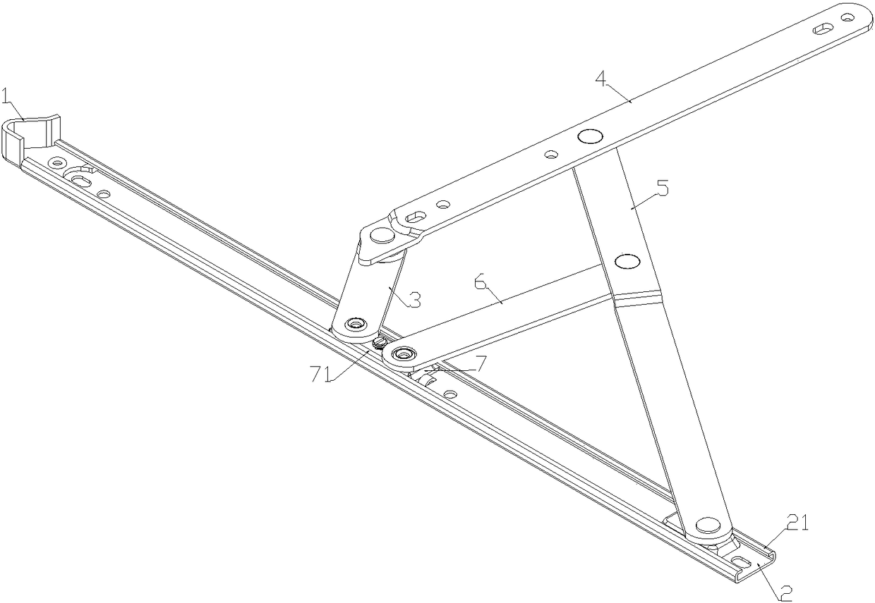
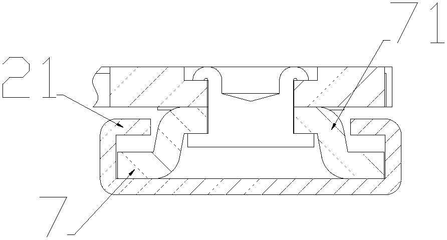
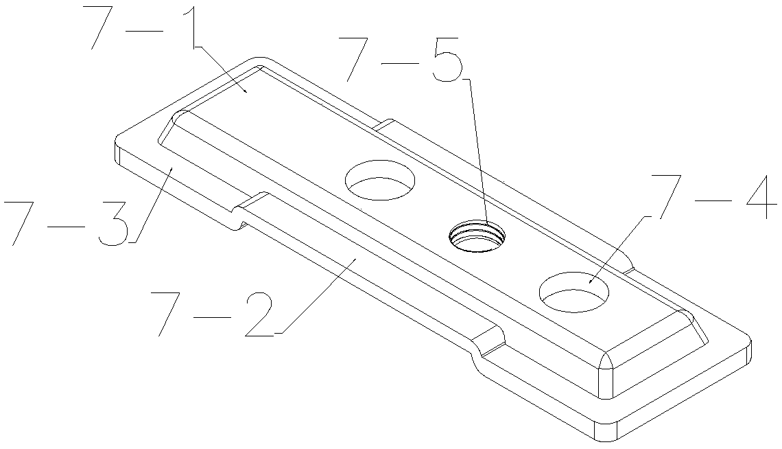
[0037] Such as Figure 2a-2b As shown, a slider is stamped from a 1.5-2mm thick copper plate; the middle of the slider 7 block is stamped with an upward protrusion 7-1, and the protrusion 7-1 is left with the edge of the slider 7. There is a distance, and the protrusion 7-1 is similar to a rectangular table or other ellipsoidal shapes. This shape has good stability and is beneficial to strengthen the load-bearing capacity of the slider 7; the two longer sides 7-3 of the slider 7 The middle section is punched into an upwardly convex middle part 7-2, so that the two sides 7-3 form a stepped shape with a convex middle and low sides. The height of the middle part 7-2 is slightly smaller than that of the slide rail to be installed. The height of the inner space from the upper flange 2-1 to the bottom of the sli...


PUM


Abstract

The invention discloses a sliding block of a sliding supporting hinge for a window. A protruding part is arranged in the middle of a sliding block body. The middle sections of the two side edges of the protruding part of the sliding block are stamped into middle parts which protrude upwards, and the height of the middle parts is matched with the height of the internal space of a sliding rail of the sliding supporting hinge. According to the sliding block of the sliding supporting hinge for the window, under the condition that the width and height of an existing sliding rail are not changed, improvement is conducted in cooperation with the internal space of the sliding rail, and the problem of an up-down gap between the sliding block and the sliding rail is well solved while the bearing capacity of the sliding block is guaranteed; the sliding block is high in structural stability, high in strength and good in abrasion resistance; and in addition, aging and deformation are avoided, and the service life of the sliding supporting hinge can be prolonged easily. In addition, the invention provides the sliding supporting hinge provided with the sliding block. The sliding supporting hinge provided with the sliding block has the high bearing capacity and can be used for opening and closing the window smoothly.

Description

Technical field [0001] The invention belongs to the technical field of sliding support hinges for windows, and in particular relates to a sliding block of sliding hinges for windows, and in particular to a sliding block hinge including the sliding blocks. Background technique [0002] The sliding support hinge for the window is a movement mechanism assembled by the sliding rail 2, the sliding block 7, a number of mutually hinged rods and the guide vertex 11; specifically including: a short support cantilever 3, a support cantilever 6 and the corresponding sliding block After being hinged, the slide rail 2 is installed, between the short support cantilever 3, the top support cantilever 4, the support cantilever 6 and the long support cantilever 5, and the long support cantilever 5 and the slide rail 2 are also hinged accordingly to form a motion mechanism; slide rail 2 One end is equipped with a guide vertex 1, reference Figure 1a , To guide the opening and closing of the hinge; d...

Claims


Application Information

Patent Timeline
Patent Type & Authority Patents(China)
IPC IPC(8): E05C17/32
CPCE05C17/32
Inventor 陈大川
Owner GUANGDONG AURICAN HARDWARE TECH CO LTD
Learn More