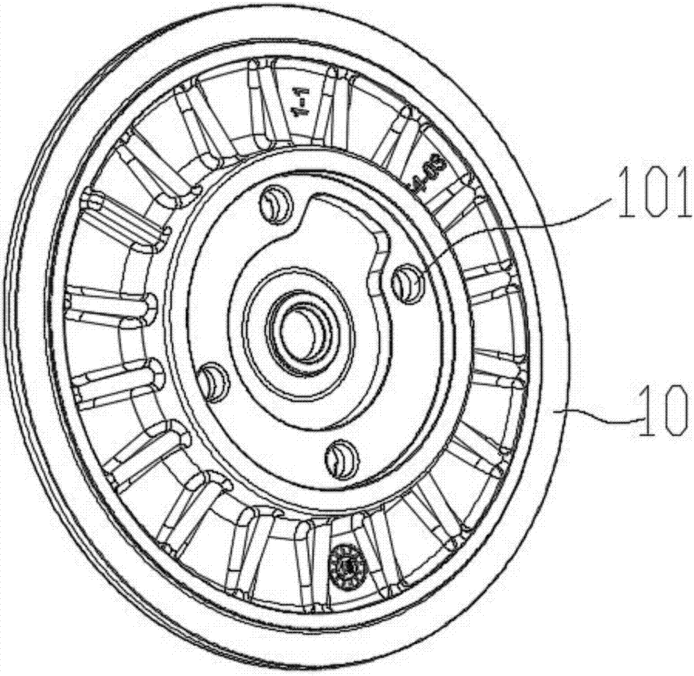
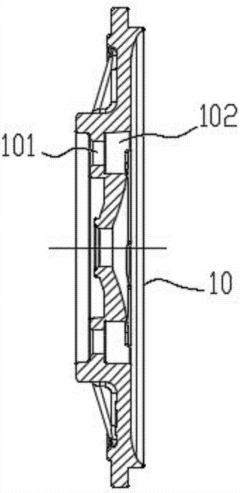
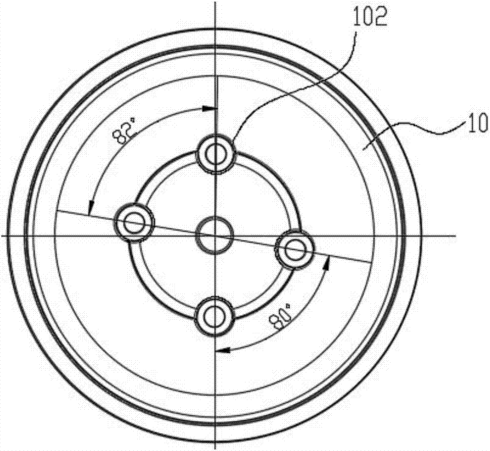
Internal expansion type tensioning fixture for end cover sealing plate
A technology of end cover sealing and clamping, which is applied in the direction of clamping, manufacturing tools, supports, etc., and can solve the problem of damage to the sealing performance and pressure performance of the end cover sealing plate, affecting the forming quality of the end cover sealing plate, and the processing offset of the peripheral edge, etc. problem, to achieve stable clamping, prevent clamping deformation, and low manufacturing cost
- Summary
- Abstract
- Description
- Claims
- Application Information
AI Technical Summary
Problems solved by technology
Method used
Image

Examples
Embodiment Construction
[0038] In order to enable those skilled in the art to better understand the technical solution of the present invention, the present invention will be described in detail below in conjunction with the accompanying drawings. The description in this part is only exemplary and explanatory, and should not have any limiting effect on the protection scope of the present invention. .
[0039] Such as Figure 4-Figure 17 As shown, the specific structure of the present invention is: an internal expansion type end cover sealing plate tensioning fixture, which includes a base 1, a pull rod 7 is arranged at the center of the base 1; the upper end of the pull rod 7 is connected to the sliding seat 2; The sliding seat 2 is arranged in the sliding groove 13 at the upper end of the machine base 1; the top of the machine base 1 is fixedly provided with a fixed seat 3; the fixed seat 3 includes a disc-shaped chassis 35 and a fixed column 31 at the center of its upper end The upper edge of the ...
PUM
 Abstract
Description
Claims
Application Information
 - R&D
- Intellectual Property
- Life Sciences
- Materials
- Tech Scout
- Unparalleled Data Quality
- Higher Quality Content
- 60% Fewer Hallucinations
Browse by: Latest US Patents, China's latest patents, Technical Efficacy Thesaurus, Application Domain, Technology Topic, Popular Technical Reports.
© 2025 PatSnap. All rights reserved.Legal|Privacy policy|Modern Slavery Act Transparency Statement|Sitemap|About US| Contact US: help@patsnap.com