Self-reinforced self-charging separate-excitation switch reluctance generator converter and control method thereof

A switched reluctance and self-charging technology, which is applied to control the direction of the generator through the change of the magnetic field, can solve the problems of expensive cables for power generation and transmission, increased manual maintenance, and large voltage and current fluctuations, so as to reduce maintenance workload, Effects of saving cost and improving power output capability

Active Publication Date: 2017-08-15
CHINA JILIANG UNIV
View PDF4 Cites 10 Cited by
  • Summary
  • Abstract
  • Description
  • Claims
  • Application Information

AI Technical Summary

Problems solved by technology

[0005] The excitation phase of the switched reluctance generator is generally controlled, while the current in the power generation phase is not strictly controlled. In order to improve the power generation output capacity, increase the current at the beginning of the power generation phase, that is, increase the current value in the excitation phase, especially in the later stage of excitation It has become one of the consensus in the industry; the industry has already used a special high-voltage separate excitation power supply to supply excitation to the winding, but the structure is complicated. If the inverter circuit itself can improve the excitation capacity, the structure will be simplified and the cost will be saved; Regardless of the excitation, it is the expectation of the industry to increase the winding current to a certain height in the shortest possible time before the power generation stage arrives.
[0006] The excitation methods of switched reluctance generators are commonly used as separate excitation type and self-excitation type. The excitation phase of the separate excitation type has good stability, but requires a separate external excitation power supply. After the power supply is exhausted, it must be replaced frequently, which increases manual maintenance. The traditional self-excitation type has the disadvantage of large voltage and current fluctuations and poor stability; therefore, an excitation power supply system with good stability and no need for too much manual participation is the expectation of the industry
[0007] In addition, cables for power generation and transmission of large and medium-sized switched reluctance generator systems are expensive, especially for submarine cables required for offshore wind power systems; and the bus voltage in large and medium-sized switched reluctance generator systems is often significantly greater than the average excitation voltage , to avoid the problem that the bus voltage penetrates the excitation power supply; there are also factors such as the use of battery excitation, the battery itself needs to be charged, different requirements for charging power at different stages, different charging speeds under different charging parameters, and whether it can be automatically charged, etc.

Method used


Image

  • Self-reinforced self-charging separate-excitation switch reluctance generator converter and control method thereof

Examples


Embodiment Construction

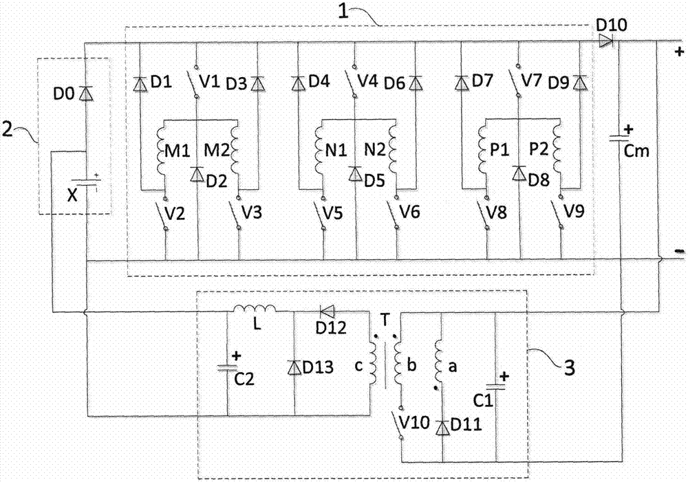
[0031] Self-strengthening self-charging separately excited switched reluctance generator converter, the circuit structure is as attached figure 1 As shown, it is composed of inverter main circuit 1, excitation power supply 2, generator diode D10, bus capacitor Cm, and charging main circuit 3. The input ends of inverter main circuit 1 are connected to the output ends of excitation power supply 2, and the output of inverter main circuit 1 is The positive terminal is connected to the positive terminal of the bus capacitor Cm via the generator diode D10, and at the same time connected to the positive terminal of the charging main circuit 3 input. Both terminals are connected to the input negative terminal of the charging main circuit 3 at the same time, and the output terminals of the charging main circuit 3 are connected to the input terminals of the excitation power supply 2 .

[0032]The converter main circuit is composed of three converter branches connected in parallel, and e...


PUM


Abstract

The invention relates to a self-reinforced self-charging separate-excitation switch reluctance generator converter and a control method thereof. The converter is composed of a conversion main circuit, an excitation power, a power generation diode, a bus capacitor, and a charging main circuit. A positive terminal of the output of the conversion main circuit is connected in parallel with the bus capacitor and the charging main circuit by the power generation diode; the output of the charging main circuit is connected with the excitation power; and the excitation power outputs power for the conversion main circuit. Each phase of winding has two sets of parallel reinforced excitations to increase follow currents and reinforcing excitation. A separate-excitation storage battery is charged automatically by using the bus voltage through the controllable charging main circuit.

Description

technical field [0001] The invention relates to the field of switched reluctance motors, in particular to a main circuit of a switched reluctance generator converter of a self-strengthening excitation and self-charging separately excited excitation power supply and a control method thereof. Background technique [0002] The use of switched reluctance generators to generate electricity is a new type of electricity generation. [0003] The power generation and conversion system of the switched reluctance generator is the foundation and key of the switched reluctance generator system, and it is also related to the efficiency, benefit and reliability of power generation. [0004] According to the working principle of the switched reluctance generator, its work is divided into two stages: excitation and power generation. First, the external power supply supplies power to the windings for excitation energy storage, and then under the action of the reverse torque of the operation, ...

Claims


Application Information

Patent Timeline
Patent Type & Authority Applications(China)
IPC IPC(8): H02P9/38
CPCH02P9/38
Inventor 孙冠群
Owner CHINA JILIANG UNIV
Why Eureka
Try Eureka