
Automatic test bench for release bearing of automobile clutch

A technology for separating bearings and clutches, applied in bearing-related force sensors, instruments, measuring devices, etc., can solve the problems of inability to realize full online detection of bearings, unstable test data, and low efficiency.

Inactive Publication Date: 2017-08-15
SOUTHEAST UNIV
View PDF5 Cites 5 Cited by
  • Summary
  • Abstract
  • Description
  • Claims
  • Application Information

AI Technical Summary

Problems solved by technology

[0004] Many famous domestic bearing enterprises and scholars have conducted a lot of research on clutch bearing test equipment based on the above-mentioned industry standards, and formed two types of representative test equipment: one is spring tension and compression testing machine equipped with simple test tooling The way to measure the self-aligning force of the release bearing has a simple mechanism and is convenient for testing, but the measurement is not accurate, the efficiency is low, and it is not convenient to record the test data; the other is the ARM-based tester for the self-aligning force of the release bearing. Simple and relatively high precision, but it is only suitable for random inspection, the test efficiency is low, and it cannot realize the online full detection of bearings
Therefore, the existing separation bearing detection methods and equipment not only have low test efficiency and unstable test data, but also are difficult to realize the automatic online test and data recording of the centering force and the amount of centering, and cannot automatically identify and reject unqualified products, and cannot adapt to separation. Bearing high-precision, fast test requirements

Method used


Image

  • Automatic test bench for release bearing of automobile clutch
  • Automatic test bench for release bearing of automobile clutch
  • Automatic test bench for release bearing of automobile clutch

Examples


Embodiment Construction

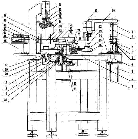
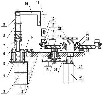
[0025] Such as figure 1 , figure 2 The shown automatic test bench for release bearing of automobile clutch includes a frame 1 welded by square steel, and adjustable anchor bolts are arranged at the back end of the frame 1 . A platform 2 is fixedly connected to the frame 1, and the platform 2 is made of a steel plate.

[0026] Vertical shaft 21 is erected fixedly at the central position of platen 2, and the axis line of vertical shaft 21 is perpendicular to the plate surface of platen 2, and vertical shaft bearing 24 that is arranged side by side and is made of two ball bearings is housed on vertical shaft 21, and vertical shaft bearing 24 is fixedly placed in the bearing seat 25 through its outer ring, and the bearing seat 25 is fixedly connected with the turntable 16. This structure makes the turntable 16 rotatably mounted on the vertical shaft 21. A gear shaft 19 is rotatably installed on the platen 2 through a gear shaft bearing 18. The upper and lower ends of the gear s...


PUM


Abstract

The invention discloses an automatic testing platform for an automobile clutch release bearing, which comprises a frame, on which a vertical shaft is fixedly installed on the platform, and a rotatable turntable is installed on the vertical shaft; an offset cylinder is also fixedly installed on the vertical shaft; A detection cylinder is fixedly supported on the platen, and the detection cylinder is connected with a pressure sensor through a sensor seat, and a displacement sensor is fixedly installed on the detection cylinder, and a weight is suspended between the pressure sensor and the push plate; There is a positioning rod that can slide in the vertical direction. The positioning rod is driven by a positioning cylinder fixedly installed on the table. The positioning rod and the weight are on the same straight line; A loading and unloading cylinder is fixedly installed on the loading and unloading rotating shaft, and a loading and unloading swing arm is connected to the loading and unloading cylinder, and a pneumatic finger is installed on the loading and unloading swing arm. The automatic detection platform not only has high test efficiency and accurate data, but also realizes automatic online detection.

Description

technical field [0001] The invention relates to a detection device for an automobile clutch release bearing, in particular to a detection device for the centering force and centering amount of the automobile clutch release bearing. Background technique [0002] The release bearing device is an important part of the automobile clutch system. The clutch release bearing is installed between the clutch pressure plate and the clutch fork, and the clutch fork is fixed together with a circlip; through the axial movement of the release bearing device, the clutch clutch is implemented. , so as to cut off or connect the power connection between the engine and the transmission system, and complete operations such as starting, stopping and shifting of the car. [0003] Under the radial load caused by eccentricity, the release bearing is likely to cause additional vibration, radial sliding friction and wear, resulting in temperature rise, vibration and noise, and the greater the eccentri...

Claims


Application Information

Patent Timeline
IPC IPC(8): G01B21/24G01L5/00
CPCG01B21/24G01L5/0009G01L5/0061
Inventor 周怡君吴勇超王玉立罗晨
Owner SOUTHEAST UNIV
Learn More