
Doped gas energy dissipation and gas explosion preventing flood discharging device and flood discharging method thereof

An energy dissipation and gas-proof technology, which is applied in water conservancy projects, sea area projects, coastline protection, etc., can solve the problems of unstable flow state, non-separation of gas and water, and blockage of gas collection chambers by soil, so as to improve stability and increase The effect of head loss

Pending Publication Date: 2017-08-15
FUJIAN PROVINCIAL INVESTIGATION DESIGN & RES INST OF WATER CONSERVANCY & HYDROPOWER
View PDF5 Cites 4 Cited by
  • Summary
  • Abstract
  • Description
  • Claims
  • Application Information

AI Technical Summary

Problems solved by technology

[0005] In order to overcome the shortcomings of monotonous structure of the energy dissipation box in the traditional flood tunnel and the narrow exhaust method of the water outlet, the present invention solves the above technical problems. The transitional connection form to the flood discharge branch tunnel adopts the combined energy dissipation technology of the swirl shaft-vertical slot energy dissipation box, and the connection form between the flood discharge branch tunnel and the exhaust well adopts the gas collection chamber-horizontal plate combined exhaust technology, which solves the problem of flow water When reaching the flood discharge branch tunnel, the flow state is unstable, the air and water are not separated, and the soil blocks the air collection chamber.

Method used


Image

  • Doped gas energy dissipation and gas explosion preventing flood discharging device and flood discharging method thereof
  • Doped gas energy dissipation and gas explosion preventing flood discharging device and flood discharging method thereof
  • Doped gas energy dissipation and gas explosion preventing flood discharging device and flood discharging method thereof

Examples


Embodiment 1

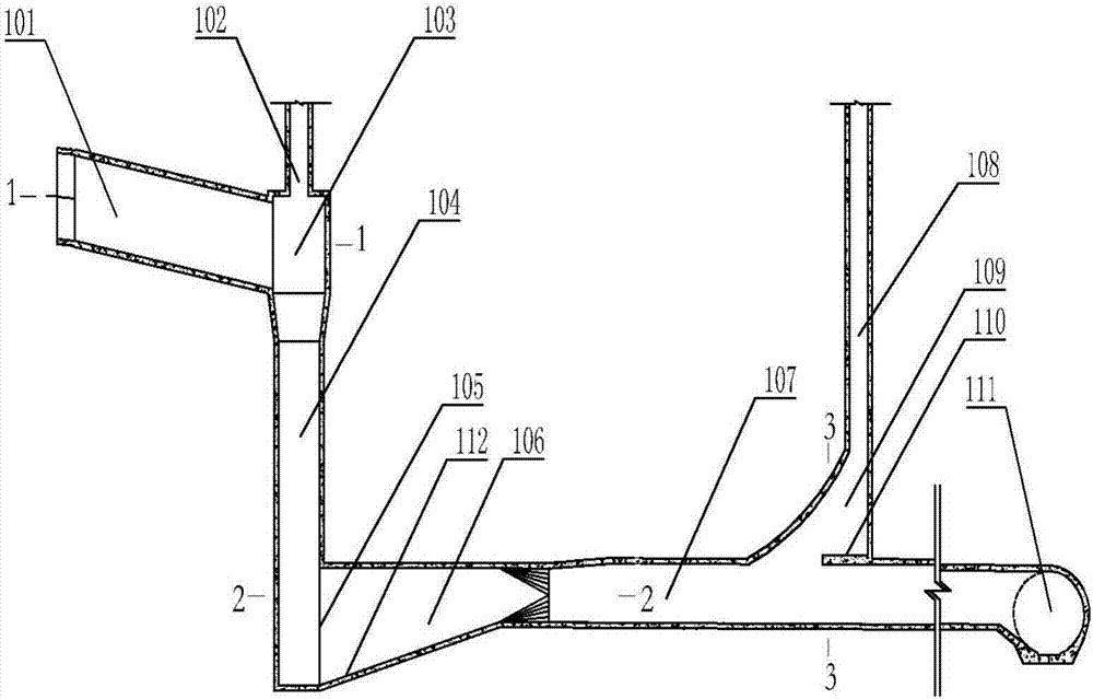
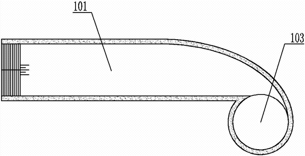
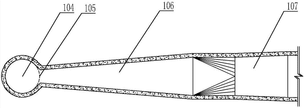
[0028] The present invention provides an aerated energy dissipation and anti-air explosion flood discharge device, as shown in Figure (1-4), which specifically includes a connecting section 101, a vent hole 102, a vortex chamber 103, a shaft 104, a vertical seam 105, an energy dissipation box 106, and a flood discharge branch hole 107, exhaust hole 108), gas collection chamber 109, horizontal plate 110, flood discharge main hole 111; the top of the shaft 104 is connected to the vortex chamber 103, and the top of the vortex chamber 103 is provided with the ventilation hole 102, The side of the vortex chamber 103 is connected to the connecting section 101, the bottom of the shaft 104 is connected to the horizontal energy dissipation box 106, and the joint between the bottom of the shaft 104 and the horizontal energy dissipation box 106 is provided with the The vertical seam 105, the energy dissipation box 106, the flood discharge branch hole 107, and the flood discharge main hole...


PUM


Abstract

The invention discloses a doped gas energy dissipation and gas explosion preventing flood discharging device and a flood discharging method thereof. The device comprises a connecting section, a ventilation hole, a volute chamber, a vertical well, a vertical gap, an energy dissipation box, a branch flood discharging cavity, an exhaust hole, a gas collecting chamber, a transverse plate and a main flood discharging cavity. The top end of the vertical well communicates with the volute chamber, and the ventilation hole is formed in the top end of the volute chamber. The side face of the volute chamber communicates with the connecting section. The bottom of the vertical well communicates with the horizontal energy dissipation box in a penetration manner. The vertical gap is arranged at the linkage position of the bottom of the vertical well and the horizontal energy dissipation box. The energy dissipation box, the branch flood discharging cavity and the main flood discharging cavity are sequentially in communication in a penetration manner. The branch flood discharging cavity vertically communicates with the gas collecting chamber along the way, and the top of the gas collecting chamber communicates with the exhaust hole. According to the flood discharging method, the rotational flow vertical well-vertical gap energy dissipation box combined energy dissipation technology is adopted in the form of transition connecting from the vertical well to the branch flood discharging cavity, the gas collecting chamber and transverse plate combined exhaust technology is adopted in the branch flood discharging cavity and exhaust well connecting form, and the problems that when flowing water reaches the branch flood discharging cavity, the flow state is not stable, gas and water are not separated, and mud blocks the gas collecting chamber are solved.

Description

technical field [0001] The invention belongs to the technical field of water conservancy energy dissipation and flood discharge, and in particular relates to an aeration energy dissipation and anti-air explosion flood discharge device and a flood discharge method thereof. Background technique [0002] The swirling flood discharge tunnel is a form of energy dissipation in which a diversion tunnel is transformed into a permanent flood discharge tunnel. Swirling flood discharge tunnels can be divided into vertical shaft swirling energy dissipation and horizontal swirling energy dissipation depending on the location where the swirling water flow occurs. The principle is to use the centrifugal force of swirling water flow to form a cavity, increase the wall pressure and hydraulic friction, and prolong the process flow. , to achieve the purpose of preventing cavitation and energy dissipation. The swirling shaft flood discharge tunnel is generally composed of four parts: the diver...

Claims


Application Information

Patent Timeline
IPC IPC(8): E02B8/06
CPCE02B8/06
Inventor 高梦露杨首龙薛泷辉付开雄何承农王乐乐叶丽清
Owner FUJIAN PROVINCIAL INVESTIGATION DESIGN & RES INST OF WATER CONSERVANCY & HYDROPOWER
Learn More