
Automatic wire harness winding device

A winding device and wire harness technology, which is applied in the field of wire harnesses, can solve the problems of laborious and laborious, different sizes and shapes of wire coils, and low efficiency of manual winding

Inactive Publication Date: 2017-08-15
WUHU QIAOYUN & YOUXING ELECTRICAL IND CO LTD
View PDF8 Cites 5 Cited by
  • Summary
  • Abstract
  • Description
  • Claims
  • Application Information

AI Technical Summary

Problems solved by technology

At present, the section of wire harness coming out of the wire cutting machine is thick and long. In order to facilitate transportation, manual winding is generally used, but the efficiency of manual winding is very low, laborious and laborious, and the size and shape of the wire coils after winding are different. It brings great difficulties to the standardization and transportation of wire harness packaging

Method used


Image

  • Automatic wire harness winding device
  • Automatic wire harness winding device
  • Automatic wire harness winding device

Examples


specific Embodiment approach

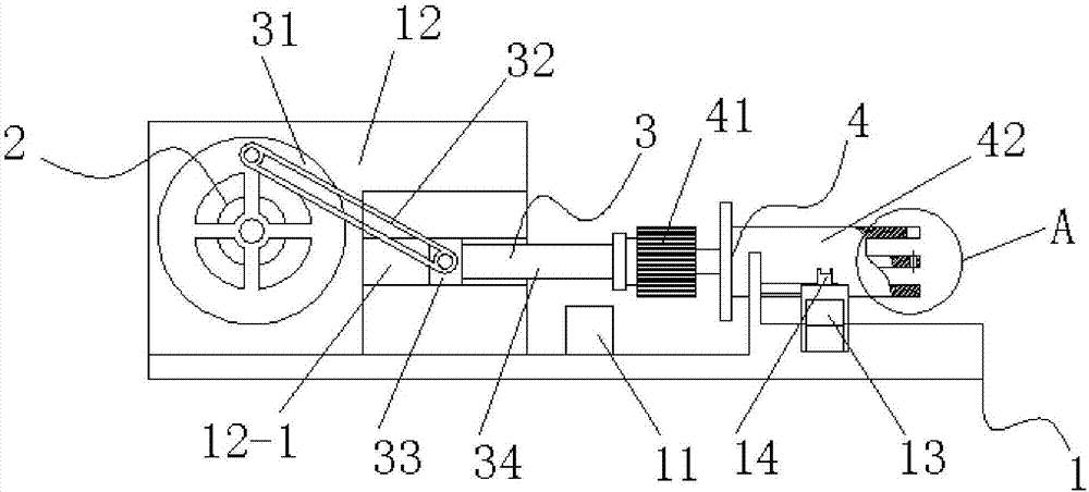
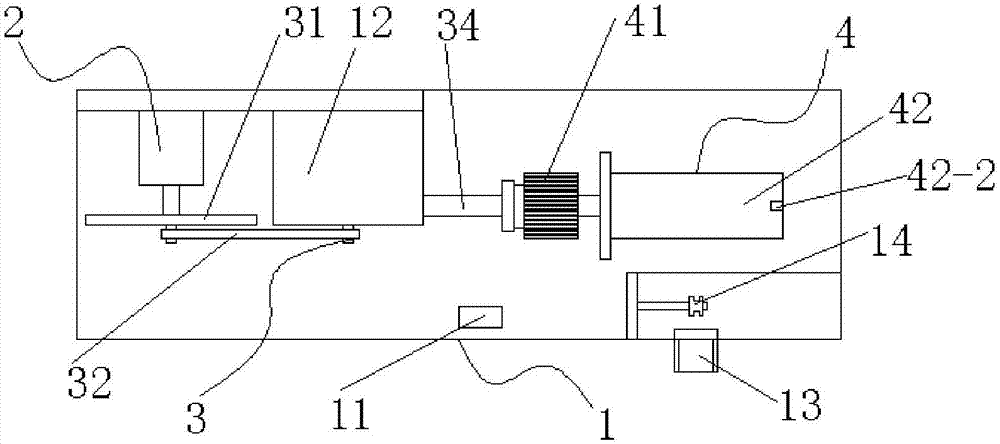
[0015] Such as Figure 1 to Figure 3 Shown is a specific embodiment of the present invention: a wire harness automatic winding device, including a device seat 1, a drive motor 2, a centering slider mechanism 3 and a winding mechanism 4, and the device seat 1 is provided with a controller 11 , vertical wall 12, wiring harness inlet 13 and guide wheel 14, described vertical wall 12 side is provided with chute 12-1, described driving motor 2 is fixedly installed on vertical wall 12 side, described centering slider mechanism 3 is connected with on the one hand The output shaft of the driving motor 2 is fixedly connected, and on the other hand is fixedly connected with the winding mechanism 4 .

[0016] In this embodiment, the centering slider mechanism 3 is composed of a runner 31, a connecting rod 32, a slider 33 and an extension rod 34. The center of the runner 31 is fixedly connected to the output shaft of the driving motor 2, and the connecting One end of the rod 32 is hinged...

Embodiment 1

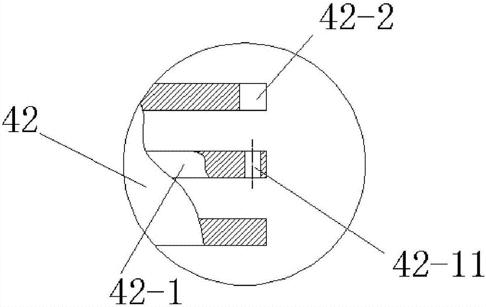
[0021] This invention is a wire harness automatic winding device. When winding the wire harness, the wire harness is now passed through the wire harness inlet 13, bypassed the guide wheel 14, and then the wire harness is passed through the wire harness through the slot 42-2 and then inserted into the wire harness fixing rod. 42-1 fixed in the fixing hole 42-11, and then turn on the drive motor 2 and the rotary motor 41 through the controller 11, the rotary motor 41 drives the wire harness winding drum 42 to rotate, and the drive motor 2 drives the runner 31 to rotate in a circular motion. Rod 32 just carries slide block 33 and does reciprocating linear motion in chute 12-1, because one end of extension rod 34 is fixedly connected with slide block 33, and the other end is fixedly connected with winding mechanism 4, slide block 33 does reciprocating linear motion to drive The winding mechanism 4 performs synchronous reciprocating linear motion, so the wire harness winding drum 42...


PUM


Abstract

The invention discloses an automatic wire harness winding device. The automatic wire harness winding device comprises a device base, a drive motor, an alignment sliding block mechanism and a winding mechanism. The device base is provided with a controller, a vertical wall, a wire harness inlet and a wire guiding wheel. A sliding groove is formed in one side of the vertical wall, and the drive motor is fixedly arranged on one side of the vertical arm. On one hand, the alignment sliding block mechanism is fixedly connected with an output shaft of the drive motor, and on the other hand, the alignment sliding block mechanism is fixedly connected with the winding mechanism. According to the device, workers do not need to conduct manual winding, the labor intensity of the workers is reduced, the work efficiency is improved, meanwhile, wound wire harnesses are standard in shape and size, and great convenience is brought to wire harness package standardization and transportation.

Description

technical field [0001] The invention belongs to the technical field of wire harnesses, in particular, the invention relates to an automatic wire harness winding device. Background technique [0002] In the industrial and civilian fields, wire harnesses are very common electronic devices, and people use wire harnesses for power, signal, etc. connections. In the wire harness production process, the cable needs to be cut into a section of wire harness with a specified length through the wire cutting mechanism before entering the next process. At present, the section of wire harness coming out of the wire cutting machine is thick and long. In order to facilitate transportation, manual winding is generally used, but the efficiency of manual winding is very low, laborious and laborious, and the size and shape of the wire coils after winding are different. It brings great difficulties to the standardization and transportation of wire harness packaging. Contents of the invention ...

Claims


Application Information

Patent Timeline
Patent Type & Authority Applications(China)
IPC IPC(8): B65H57/14B65H54/547B65H57/28
CPCB65H57/14B65H54/547B65H57/28B65H2701/30
Inventor 周忠周顺刘陆明辛文彬晋秀兰
Owner WUHU QIAOYUN & YOUXING ELECTRICAL IND CO LTD
Learn More