Efficient test tube cleaning machine

A technology for cleaning machines and test tubes, which is applied in the direction of cleaning hollow objects, cleaning methods and utensils, chemical instruments and methods, etc. It can solve the problems of difficulty in meeting laboratory cleaning needs, increasing the workload of experimenters, and low cleaning efficiency of test tube brushes. Achieve the effects of saving experiment preparation time, high practical value, and low manufacturing cost

Inactive Publication Date: 2017-08-15
屈丽艳
View PDF0 Cites 7 Cited by
  • Summary
  • Abstract
  • Description
  • Claims
  • Application Information

AI Technical Summary

Problems solved by technology

[0002] The test tube is a basic experimental instrument commonly used in the laboratory. In order to avoid the reduction of the experimental accuracy caused by the mixing of reagents during the experiment, the test tube needs to be cleaned after each use. The traditional test tube cleaning process mainly uses a test tube brush for cleaning. Due to the test tube brush cleaning The efficiency is low, the operation is cumbersome, and the labor intensity is high, which increases the workload of the experimenters. Therefore, it is difficult to meet the cleaning needs of the laboratory. If a new type of cleaning method can be invented that is simple to operate, high in cleaning efficiency, and can effectively reduce the labor intensity of the experimenters The test tube cleaning device can solve such problems, for which we provide a high-efficiency test tube cleaning machine

Method used


Image

  • Efficient test tube cleaning machine
  • Efficient test tube cleaning machine

Examples


Embodiment Construction

[0011] The following will clearly and completely describe the technical solutions in the embodiments of the present invention with reference to the accompanying drawings in the embodiments of the present invention. Obviously, the described embodiments are only some, not all, embodiments of the present invention. Based on the technical solutions in the present invention, all other embodiments obtained by persons of ordinary skill in the art without making creative efforts belong to the protection scope of the present invention.

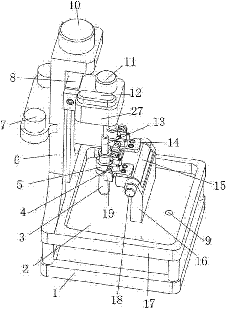
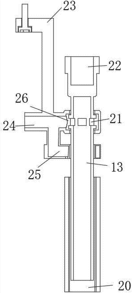
[0012] see Figure 1-2 , the present invention provides a technical solution: a high-efficiency test tube cleaning machine, including a base 1, and the upper end of the base 1 is provided with a support plate 17, and the rear end of the support plate 17 is provided with a column 6, and the column 6 is provided with a lifting platform 8. The upper end of the column 6 is provided with a screw drive motor 10 for driving the lifting platform 8, and at leas...


PUM


Abstract

The invention discloses a high-efficiency test tube cleaning machine, which comprises a base, and a support plate is arranged at the upper end of the base, and a column is arranged at the rear end of the support plate, and a lifting platform is arranged on the column, and a driving platform is arranged at the upper end of the column. The screw drive motor of the lifting platform, and at least two cleaning seats are installed on the lifting platform, a rotating motor is installed on the cleaning seats, and a cleaning head is provided at the lower end of the cleaning seat, and a cleaning head is provided at the upper end of the cleaning head for connecting The screw connection pipe of the output shaft of the rotating motor, and the lower end of the cleaning head is socketed with a socket-type brush head. The test tube cleaning machine designed by the present invention replaces the traditional manual cleaning operation of the test tube with an automatic cleaning method, which can effectively reduce the work of the experimenter. The utility model has the advantages of high strength, saving experiment preparation time, reasonable structure design and low manufacturing cost, which can meet the needs of various laboratories and has high practical value.

Description

technical field [0001] The invention relates to the technical field of experimental equipment, in particular to a high-efficiency test tube cleaning machine. Background technique [0002] The test tube is a basic experimental instrument commonly used in the laboratory. In order to avoid the reduction of the experimental accuracy caused by the mixing of reagents during the experiment, the test tube needs to be cleaned after each use. The traditional test tube cleaning process mainly uses a test tube brush for cleaning. Due to the test tube brush cleaning The efficiency is low, the operation is cumbersome, and the labor intensity is high, which increases the workload of the experimenters. Therefore, it is difficult to meet the cleaning needs of the laboratory. If a new type of cleaning method can be invented that is simple to operate, high in cleaning efficiency, and can effectively reduce the labor intensity of the experimenters The test tube cleaning device can solve such pr...

Claims


Application Information

Patent Timeline
Patent Type & Authority Applications(China)
IPC IPC(8): B08B9/36B08B9/28
CPCB08B9/36B08B9/28
Inventor 屈丽艳
Owner 屈丽艳
Why Eureka
Try Eureka