Multi-chamber rotary furnace and numerical simulation method for performing catalyst particle heating

A rotary kiln and catalyst technology, applied in 3D modeling, image data processing, electrical digital data processing, etc., can solve the problems of difficult determination of related parameters, time-consuming and labor-intensive, difficult and other problems, and achieve good drying effect, low energy consumption, high efficiency effect

Inactive Publication Date: 2017-08-11
SHANGHAI UNIV
View PDF2 Cites 3 Cited by
  • Summary
  • Abstract
  • Description
  • Claims
  • Application Information

AI Technical Summary

Problems solved by technology

There are many factors influencing these physical and chemical reaction processes, which are interrelated, and the relevant parameters are not easy to determine. It is time-consuming and laborious to conduct systematic research on comprehensive consideration of various factors, and it is not easy to obtain ideal results.

Method used


Image

  • Multi-chamber rotary furnace and numerical simulation method for performing catalyst particle heating
  • Multi-chamber rotary furnace and numerical simulation method for performing catalyst particle heating
  • Multi-chamber rotary furnace and numerical simulation method for performing catalyst particle heating

Examples


Embodiment 1

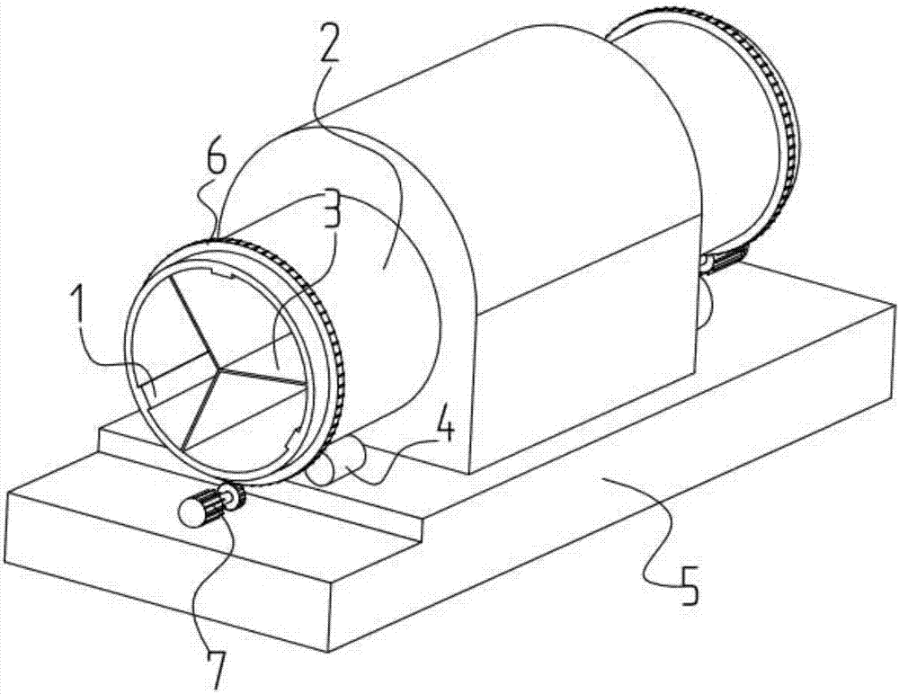
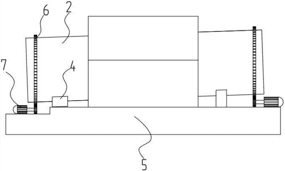
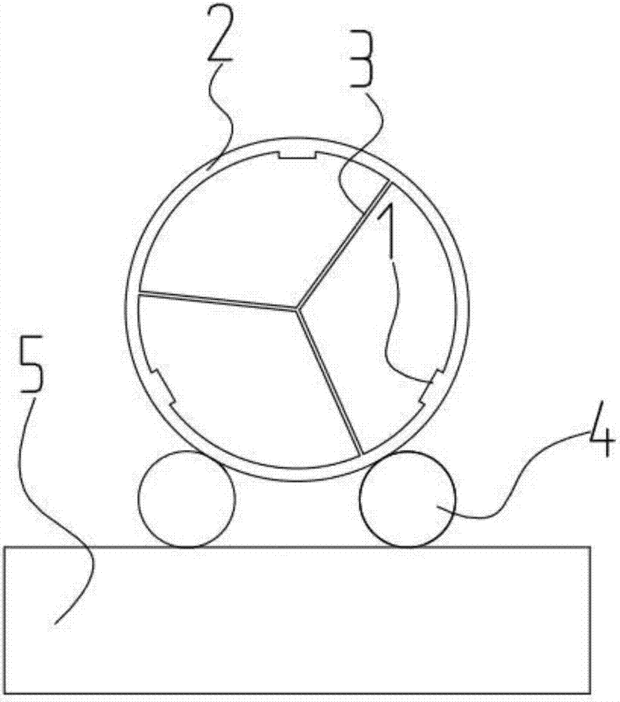
[0046] In this example, see Figure 1~4 , a multi-chamber rotary furnace, including a combustion chamber, a rotary furnace body 2 and a support platform 5, the front and rear ends of the rotary furnace body 2 are rotatably mounted on the support platform 5, and the hot end of the heating device 9 arranged in the combustion chamber The heating section of the rotary furnace body 2 can be heated. The rotary furnace body 2 is rotatably installed in the combustion chamber. The outer wall of the front end of the rotary furnace body 2 outside the room is fixedly connected to the outer ring gear 6, and the drive motor 7 is fixedly installed on the support table 5. The drive motor 7 drives the outer ring gear 6 through the gear transmission mechanism, and then drives the rotary furnace body 2 to rotate. Three heat conducting plates 3 are fixedly installed in the inner cavity of the rotary furnace body 2, and each heat conducting plate 3 is extended and installed along the axis of the r...

Embodiment 2

[0082] This embodiment is basically the same as Embodiment 1, especially in that:

[0083]In this embodiment, the number of heat conducting plates 3 is 4 pieces, the angle between any two adjacent heat conducting plates 3 is 90°, and the inner cavity of the rotary furnace body 2 is evenly divided into 4 equal parts; and The number of plates 1 is four. On the basis of the multi-chamber rotary furnace in this embodiment, the numerical simulation method of catalyst particle heating is carried out, and the computational fluid dynamics software CFX is used to numerically calculate the heating process of the catalyst material in the gas-fired multi-chamber rotary furnace and the accompanying heat transfer process, and also To a certain extent, it avoids the high cost and technical risks caused by experiments or blind design, and has certain guiding significance for the actual operating conditions of multi-chamber rotary furnaces.


PUM


Abstract

The invention discloses a multi-chamber rotary furnace, which is scientific and reasonable in structure, good in drying effect, low in energy consumption, low in cost, high in efficiency and easy to realize. On this basis, the invention provides a numerical simulation method for performing catalyst particle heating by utilizing the multi-chamber rotary furnace. Computational fluid dynamics software CFX is adopted to perform numerical computation on a heating process of catalyst materials in the gas multi-chamber rotary furnace and an accompanying heat transfer process, so that high cost and technical risks caused by experiments or blind design are avoided to a certain extent; and the method is of a certain guiding significance for actual operation conditions of the multi-cavity rotary furnace.

Description

technical field [0001] The invention relates to a heating furnace device and a heating furnace parameter simulation method, in particular to a rotary furnace device and a heating furnace working parameter simulation method, which are applied in the field of catalyst production and preparation devices and process technology. Background technique [0002] The petroleum and chemical industry is one of the most basic and largest three pillar industries in contemporary society, and it is closely related to the energy and material industries. Catalysts play a very important role in the petroleum and chemical industries. Catalyst heating is an integral process in its production, which can be done in a rotary kiln. For coal-fired industrial furnaces, small and medium-sized enterprises in my country generally use direct coal combustion to provide heat sources for industrial furnaces. The main problem in this combustion process of coal is that the increase, decrease and distribution...

Claims


Application Information

Patent Timeline
Patent Type & Authority Applications(China)
IPC IPC(8): G06F17/50G06T17/00
CPCG06F30/20G06T17/00
Inventor 马玉屏李盛鹏朱远戚严文魏望望刘威威许京荆
Owner SHANGHAI UNIV
Why Eureka
Try Eureka