Copper wire winding device

A wire take-up device and copper wire technology, which is applied in the directions of transportation and packaging, transportation of filamentous materials, thin material processing, etc. The effect of uniform line, simple and reasonable structure, and convenient use

Inactive Publication Date: 2017-08-11
ANHUI JIEAO ELECTRIC CO LTD
View PDF0 Cites 1 Cited by
  • Summary
  • Abstract
  • Description
  • Claims
  • Application Information

AI Technical Summary

Problems solved by technology

[0002] Copper wire is one of the main materials of cables. It is a very important material. Copper wire needs to be taken up during processing. The traditional take-up device has uneven take-up and no protective measures for copper wire, which is easy to affect the product. quality

Method used


Image

  • Copper wire winding device

Examples


Embodiment Construction

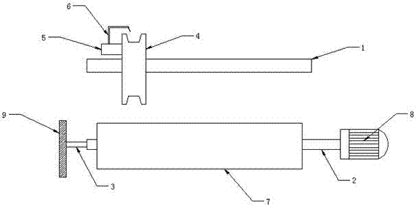
[0007] The invention will be further described below in conjunction with the accompanying drawings.

[0008] A copper wire take-up device, comprising a guide rail 1, a rotating shaft 2, a fixed shaft 3, a guide rail 4, an oil storage tank 5, an oil dripping pipe 6, a recovery pipe 7, a motor 8, and a weighing device 9. The guide rail is set on the rotating shaft 1 above, the rotating shaft 1 is set on the fixed shaft 2, the fixed shaft 2 is set on the weighing device 9, the recovery pipe 7 is set on the rotating shaft 2, the wire groove 4 is set on the guide rail 1, the The oil storage tank 5 is arranged on one side of the wire groove 4, the oil drip pipe 6 is arranged above the wire groove 4, the motor 8 is arranged on the rotating shaft 2, the wire groove 4 is movably arranged on the guide rail 1, and the oil drip pipe 6 communicates with the oil storage tank 5, the rotating shaft 2 is flexibly connected with the fixed shaft 3, the fixed shaft 3 runs through the rotating sha...


PUM


Abstract

The invention discloses a copper wire take-up device, which comprises a guide rail, a rotating shaft, a fixed shaft, a guide rail, an oil storage tank, an oil dripping pipe, a recovery pipe, a motor, and a weighing device. The guide rail is arranged above the rotating shaft, and the rotating shaft is arranged On the fixed shaft, the fixed shaft is set on the weighing device, the recovery pipe is set on the rotating shaft, the wire groove is set on the guide rail, the oil storage tank is set on one side of the wire groove, and the oil drip tube is set Above the wire groove, the motor is arranged on the rotating shaft. The invention has simple and reasonable structure and is convenient to use.

Description

technical field [0001] The invention relates to a copper wire take-up device, which belongs to the technical field of copper wire processing equipment. Background technique [0002] Copper wire is one of the main materials of cables. It is a very important material. Copper wire needs to be taken up during processing. The traditional take-up device has uneven take-up and no protective measures for copper wire, which is easy to affect the product. quality. Contents of the invention [0003] In order to overcome the above disadvantages, the object of the present invention is to provide a copper wire take-up device. [0004] The scheme of the present invention is as follows: a copper wire take-up device, comprising a guide rail, a rotating shaft, a fixed shaft, a guide rail, an oil storage tank, an oil dripping pipe, a recovery pipe, a motor, and a weighing device, the guide rail is arranged above the rotating shaft, and the The rotating shaft is set on the fixed shaft, the ...

Claims


Application Information

Patent Timeline
Patent Type & Authority Applications(China)
IPC IPC(8): B65H54/44B65H54/70B65H57/04B65H54/28
CPCB65H54/44B65H54/28B65H54/70B65H57/04B65H2701/36
Inventor 王万虎
Owner ANHUI JIEAO ELECTRIC CO LTD
Why Eureka
Try Eureka