Electric automobile charging pile integrating alternating and direct current charging functions

An electric vehicle, DC charging technology, applied in the direction of electric vehicle charging technology, electric vehicles, charging stations, etc., can solve the problems of battery life loss, function-specific, unable to meet the vehicle charging speed at the same time, etc.

Inactive Publication Date: 2017-08-11
任荣源
View PDF0 Cites 0 Cited by
  • Summary
  • Abstract
  • Description
  • Claims
  • Application Information

AI Technical Summary

Problems solved by technology

[0002] At present, the vast majority of existing electric vehicle off-board charging piles at home and abroad are divided into two different types: AC low-power slow charging and DC high-power fast charging: for AC low-power slow charging, in Electric vehicle owners are short on time and need to quickly charge the battery of the vehicle to drive immediately because of insufficient output power; for DC high-power fast charging, although its output power is larger than AC slow charging, it is enough to ensure rapid charging. Vehicles, however, have a relatively large loss of battery life. In addition, during the idle period when the power load is low, such as at night, the valley electricity charge is also lower than during the day. Therefore, at this time, instead of DC fast charging, AC slow charging is used. Even better for charging the vehicle
It can be seen that the existing non-vehicle charging piles, due to the separation of AC and DC charging output modes and output power, artificially isolate and divide charging piles with different charging speeds into different types, and the functions appear to be specific, so that it cannot be used. Simultaneously satisfying such opposing usage requirements for vehicle charging speed in these two different scenarios

Method used


Image

  • Electric automobile charging pile integrating alternating and direct current charging functions

Examples


Embodiment Construction

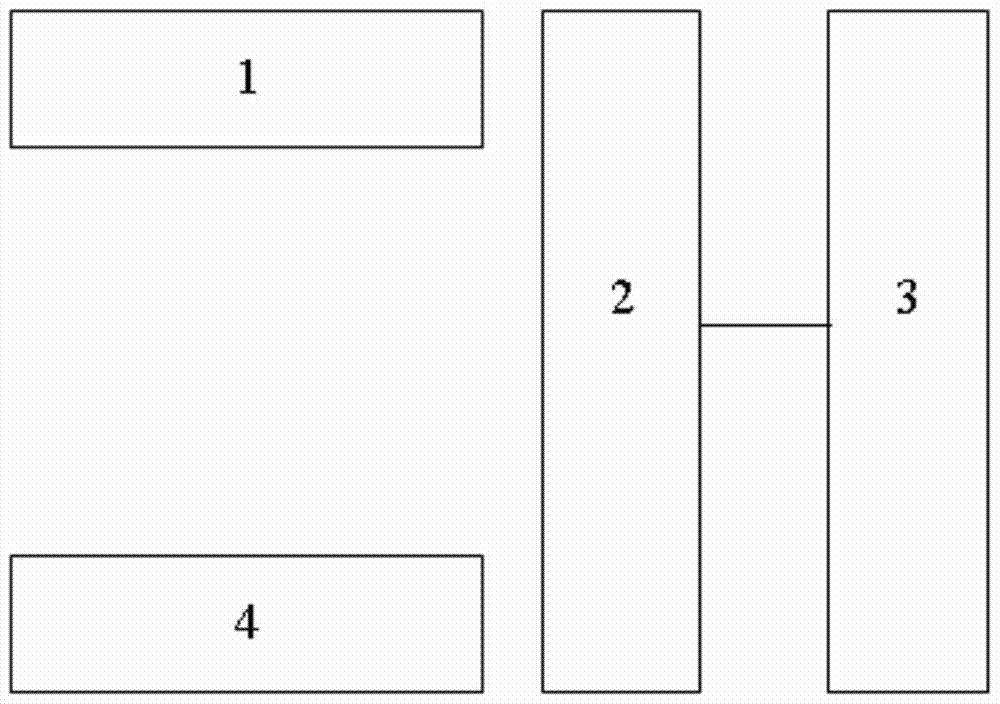
[0013] The implementation of the electric vehicle charging pile integrating AC and DC charging functions of the present invention will be described in detail below with reference to the accompanying drawings.

[0014] The technical implementation of the charging system for charging electric vehicles is as follows: in the charging system, the charger inserts the plug with a wire into the matching socket on the electric vehicle, and the electric energy is input into the battery to charge it. The charger is provided with a locking lever to facilitate insertion and removal of the plug, and the lever can also provide a signal to confirm that it has been locked to ensure safety. According to the communication between the charger and the on-board battery management system, the power converter can adjust the charging power online, and the charger can display the charging voltage, charging current, charging capacity and charging cost.

[0015] However, the charging system in the prior ...


PUM


Abstract

The invention relates to an electric automobile charging pile integrating alternating and direct current charging functions. A charging system comprises a GPS positioner, an LED lamp tube, LED drive equipment and charging voltage change ratio detection equipment. The GPS positioner is used for providing the GPS position of the charging system. The LED lamp tube and the LED drive equipment conduct cooperative operation and are used for providing streetlamp lighting for nearby places. The charging voltage change rate detection equipment is used for detecting the charging voltage change rate in real time when the charging system charges an electric automobile. The charging voltage change rate is used for determining whether the electric automobile is completely charged or not. Through the electric automobile charging pile, LED lighting, automobile charging and automobile navigation are integrated on one device, and the space occupied by urban public facilities is further saved.

Description

technical field [0001] The invention relates to the field of charging systems, in particular to an electric vehicle charging pile integrating AC and DC charging functions. Background technique [0002] At present, most of the existing off-board charging piles for electric vehicles at home and abroad are divided into two different types: AC low-power slow charging and DC high-power fast charging: for the AC low-power slow charging type, in Electric vehicle owners are short on time and need to quickly charge the battery of the vehicle to drive immediately, because of insufficient output power, they cannot meet it; for DC high-power fast charging, although its output power is larger than AC slow charging, it is enough to ensure rapid charging. Vehicles, however, have a relatively large loss of battery life. In addition, during the idle period when the power load is low, such as at night, the valley electricity charge is also lower than during the day. Therefore, at this time, i...

Claims


Application Information

Patent Timeline
IPC IPC(8): B60L11/18F21V33/00
CPCB60L53/60B60L53/665B60L58/12B60L58/13F21V33/006F21W2131/103Y02T10/70Y02T10/7072Y02T90/12Y02T90/16
Inventor 任荣源
Owner 任荣源
Why Eureka
Try Eureka