
Method for predicting junction temperature of IGBT (Insulated Gate Bipolar Translator) module

A prediction method and junction temperature technology, applied in special data processing applications, instruments, electrical digital data processing, etc., can solve problems such as low switching frequency, complex switching behavior of sub-modules, etc., achieve high precision, simple and practical algorithm, and save energy. The effect of software resources

Active Publication Date: 2017-08-08
XI AN JIAOTONG UNIV
View PDF3 Cites 22 Cited by
  • Summary
  • Abstract
  • Description
  • Claims
  • Application Information

AI Technical Summary

Problems solved by technology

The current junction temperature calculation method is mostly the IGBT junction temperature calculation method in the PWM converter. Due to the different modulation methods of the modular multi-level circuit, the switching behavior of its sub-modules is more complicated and the switching frequency is lower, so it cannot be calculated Its direct application in modular multilevel circuits

Method used


Image

  • Method for predicting junction temperature of IGBT (Insulated Gate Bipolar Translator) module
  • Method for predicting junction temperature of IGBT (Insulated Gate Bipolar Translator) module
  • Method for predicting junction temperature of IGBT (Insulated Gate Bipolar Translator) module

Examples


Embodiment Construction

[0050] The present invention is further described below in conjunction with the accompanying drawings and examples, but the present invention is not limited to the examples given.

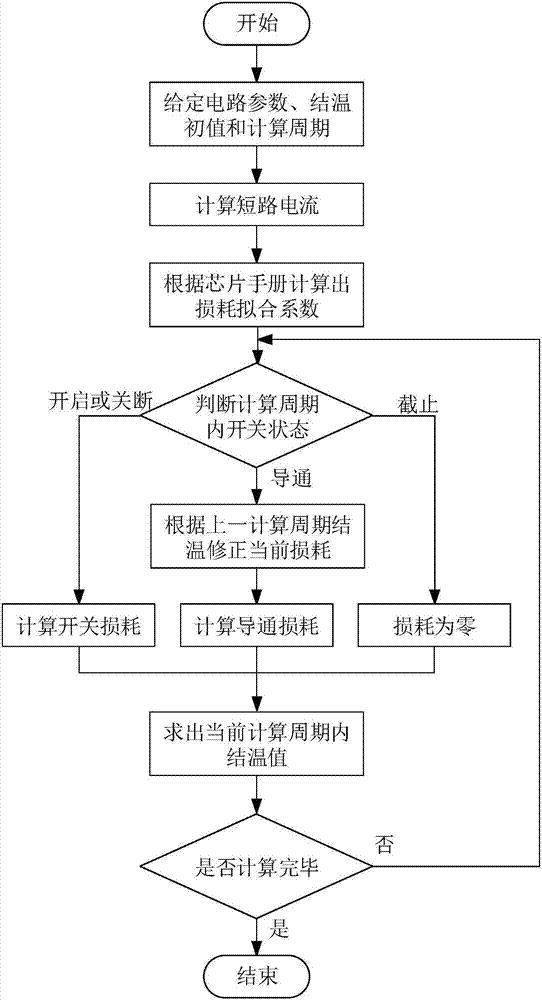
[0051] like figure 1 As shown, a junction temperature prediction method of an IGBT module provided by the present invention comprises the following steps:

[0052]The first step: before calculating, will determine the required parameter value of calculation, in the present invention, these parameters comprise:

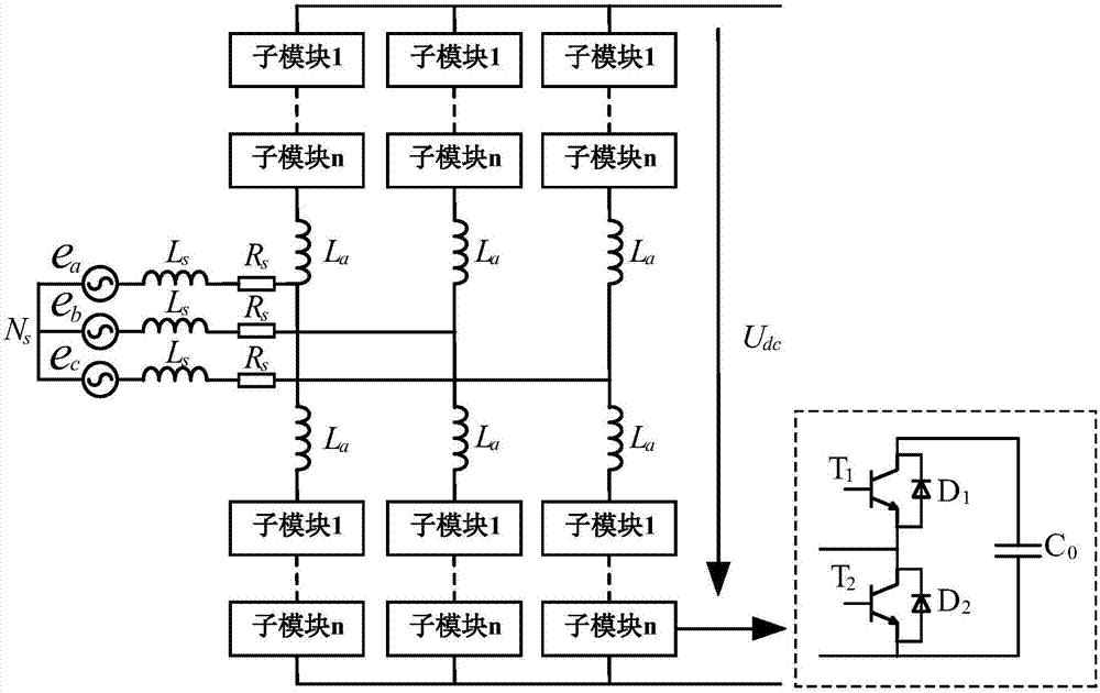
[0053] The parameters of the main circuit, such as figure 2 shown, including the DC side voltage value U dc , the number of sub-modules in half a bridge arm n, the capacitance value of sub-modules C 0 , Bridge arm valve reactor inductance L a , Bridge arm equivalent resistance R st , DC bus equivalent inductance L L and equivalent resistance R L . The bridge arm equivalent resistance includes reactor DC resistance, capacitor series equivalent resistance, line and device equivalent ...


PUM


Abstract

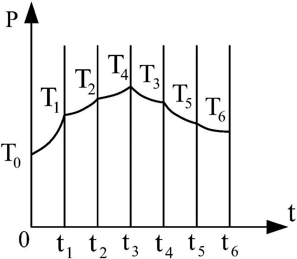
The invention discloses a method for predicting the junction temperature of an IGBT (Insulated Gate Bipolar Translator) module. The method comprises the following steps: 1) according to parameters of a modularized multi-level circuit and the running condition thereof before shortcircuit, calculating an expression of current flowing through the IGBT during direct-current bipolar shortcircuit; 2) according to an IGBT data sheet, fitting relational expressions between the conduction loss and the current flowing through the IGBT and between the switching energy and the current flowing through the IGBT; 3) according to the equivalent switching frequency and the equivalent duty ratio of the IGBT, judging the switching state of the IGBT; 4) according to the switching state of the IGBT, the expression of the current flowing through the IGBT during the direct-current bipolar shortcircuit, and the relational expressions between the conduction loss and the current flowing through the IGBT and between the switching energy and the current flowing through the IGBT, calculating a loss value P of the IGBT; 5) according to the loss value P of the IGBT and a fourth-order Foter heat transfer model of the IGBT module, calculating a distribution value of the junction temperature of the IGBT along with time. The method is applied to the modularized multi-level circuit, and is used for predicting a junction temperature change curve during the direct-current bipolar shortcircuit under different running conditions through calculation; by the method, a reference is provided for main circuit design, protection design and cooling circuit design, and the stability of a system is improved.

Description

[0001] Technical field: [0002] The invention belongs to the technical field of power electronics, and in particular relates to a junction temperature prediction method of an IGBT module, which is used for calculating the junction temperature of the IGBT under the condition of a DC bipolar short circuit of a modular multilevel circuit. [0003] Background technique: [0004] Because of its strong scalability, high output level and low harmonic content, modular multi-level is very suitable for high-voltage and high-current occasions, and has a wide range of applications in flexible direct current transmission. The IGBT (Insulated Gate Bipolar Transistor) is the most important component in the circuit sub-module, and whether it works normally or not greatly affects the reliability of the operation of the circuit. IGBT module failure is largely due to overheating failure under the influence of thermal cycle, which has a direct relationship with its junction temperature. Therefor...

Claims


Application Information

Patent Timeline
IPC IPC(8): G06F17/50
CPCG06F30/20
Inventor 王跃周晖王璋尹诗媛尹太元段国朝
Owner XI AN JIAOTONG UNIV
Learn More