
Anti-fatigue testing device of engineering mechanics

An experimental device and technology of engineering mechanics, applied in the field of fatigue test, can solve problems such as equipment failure, lack, and incomplete reset of spring expansion and contraction, and achieve the effect of wide application range and simple structure

Pending Publication Date: 2017-08-08
ANHUI UNIV OF SCI & TECH
View PDF0 Cites 2 Cited by
  • Summary
  • Abstract
  • Description
  • Claims
  • Application Information

AI Technical Summary

Problems solved by technology

[0002] Spring plays a pivotal role in engineering mechanics. It is a mechanical part that uses elasticity to work. Parts made of elastic materials are deformed under the action of external force and return to their original shape after removing the external force. When the spring is working, the force it receives It changes frequently. Under the action of alternating stress, although the stress it bears is lower than the yield point of the material, the phenomenon of cracks or sudden complete fracture after a long period of work is called metal fatigue, even if the spring It is not broken, but due to the long-term stress, the expansion and contraction of the spring cannot be completely reset, and some work cannot be completed, resulting in equipment failure. Therefore, fatigue tests need to be carried out on different batches of springs, and currently on the market Lack of a special device for testing spring fatigue strength

Method used


Image

  • Anti-fatigue testing device of engineering mechanics
  • Anti-fatigue testing device of engineering mechanics
  • Anti-fatigue testing device of engineering mechanics

Examples


Embodiment Construction

[0014] The following will clearly and completely describe the technical solutions in the embodiments of the present invention with reference to the accompanying drawings in the embodiments of the present invention. Obviously, the described embodiments are only some, not all, embodiments of the present invention.

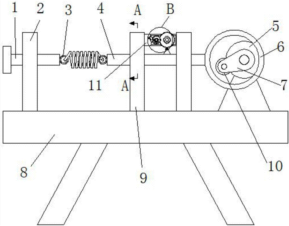
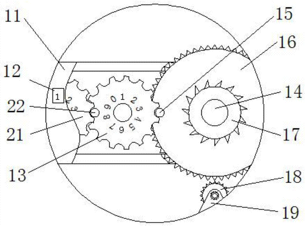
[0015] refer to Figure 1-3 , a fatigue resistance test device of engineering mechanics, including a workbench 8 and legs fixed on the bottom, the workbench 8 is provided with a motor 5, and the workbench 8 is respectively provided with a first support plate 2 and two symmetrically arranged The second support plate 9 of the first support plate 2 is threadedly connected with a screw rod 1, a slide bar 4 is arranged between the two second support plates 9, and both ends of the slide bar 4 pass through the second support plate 9, the second support plate 9 The two support plates 9 are provided with a slide corresponding to the slide bar 4, and the inwall of the slide is...


PUM


Abstract

The invention discloses a fatigue resistance experimental device of engineering mechanics, which comprises a workbench and legs fixed on the bottom thereof, a motor is arranged on the workbench, a first support plate and two symmetrically arranged The second support plate, the first support plate is threadedly connected with a screw rod, a slide bar is arranged between the two second support plates, and both ends of the slide bar pass through the second support plate, and the opposite ends of the slide bar and the screw rod are A pull ring is provided, and the end of the slide bar away from the pull ring is connected with a circular ring. The invention has a simple structure, and is used to simulate the expansion and contraction of the spring in actual use through the mutual cooperation of the motor, the cam, the ring, the slide rod and the screw rod. At the same time, using the progressive relationship between the first gear, the first sheave and the second sheave, the number of stretching times of the spring can be counted, and can be read directly through the digital label to visually display the fatigue strength of the spring.

Description

technical field [0001] The invention relates to the field of fatigue test technology, in particular to an engineering mechanics fatigue resistance test device. Background technique [0002] Spring plays a pivotal role in engineering mechanics. It is a mechanical part that uses elasticity to work. Parts made of elastic materials are deformed under the action of external force and return to their original shape after removing the external force. When the spring is working, the force it receives It changes frequently. Under the action of alternating stress, although the stress it bears is lower than the yield point of the material, the phenomenon of cracks or sudden complete fracture after a long period of work is called metal fatigue, even if the spring It is not broken, but due to the long-term stress, the expansion and contraction of the spring cannot be completely reset, and some work cannot be completed, resulting in equipment failure. Therefore, fatigue tests need to be c...

Claims


Application Information

Patent Timeline
Patent Type & Authority Applications(China)
IPC IPC(8): G01N3/38
CPCG01N3/38G01N2203/0005G01N2203/005
Inventor 吴垠洲尹梦涵胡松洁
Owner ANHUI UNIV OF SCI & TECH
Learn More