Double-tube type powder quantitative feeding device

A quantitative feeding device, tubular technology, applied in the conveyor control device, transportation and packaging, loading/unloading, etc., can solve the problems of powder conveying interruption, conveying volume deviation, bridging, etc., to achieve low cost, avoid Imported bridge and simple structure

Active Publication Date: 2017-08-08
HEFEI GOODTIMES AUTOMATION
View PDF9 Cites 2 Cited by
  • Summary
  • Abstract
  • Description
  • Claims
  • Application Information

AI Technical Summary

Problems solved by technology

[0003] The existing screw conveyors are all directly installed at the bottom of the powder silo, which causes the silo pressure exerted by the powder on the screw conveyor to be in a large fluctuation state all the time, resulting in a deviation between the delivery volume of the screw conveyor and the delivery volume at the design speed , in the existing technology, there is an attempt to solve the problem by installing an unloader between the silo and the screw conveyor, but in the case of poor powder fluidity, it often leads to a gap between the powder silo and the unloader. bridging of powders, often resulting in interruption of powder delivery
At the same time, there is also the problem of bridging when the screw conveyor is directly installed at the bottom of the powder silo

Method used


Image

  • Double-tube type powder quantitative feeding device
  • Double-tube type powder quantitative feeding device
  • Double-tube type powder quantitative feeding device

Examples


Embodiment Construction

[0023] In order to make the technical means, creative features, objectives and effects of the present invention easy to understand, the present invention will be further explained in conjunction with specific drawings.

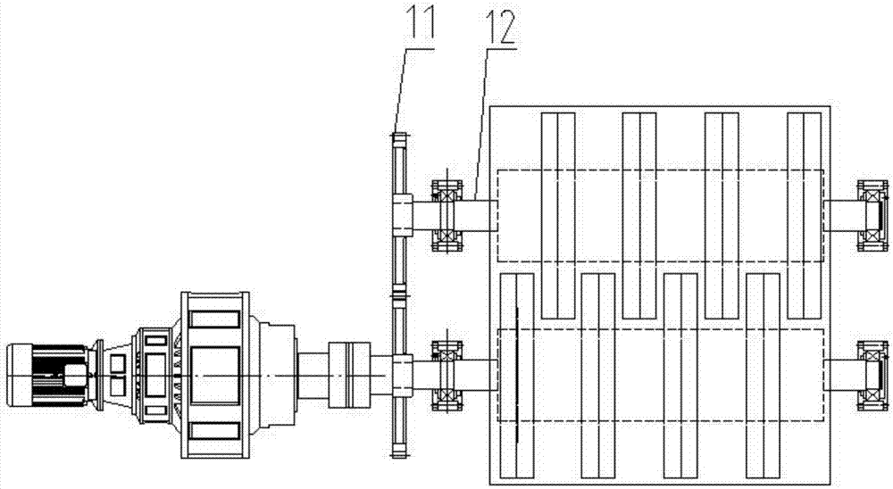
[0024] See figure 1 , figure 2 , image 3 , Figure 4 , A double-tube type powder quantitative dosing device, comprising: two sets of rotating drums 6 with opposite directions, with several sets of discharge turntables 5, and horizontal and parallel arranged drums 6; with several arc-shaped notches, at Two sets of discharging turntables 5 intersectingly arranged on two sets of rotating drums 6; two sets of splitting silos 15 whose upper part communicates with the equalizing silo 7, the bottom communicates with the screw conveyor 9, and the upper and lower parts are provided with level gauges 16;

[0025] The two sets of rotating drums 6 are respectively fixed on the transmission shaft 8 and the driven shaft 12, the front of the transmission shaft 8 is provided wit...


PUM


Abstract

The invention discloses a double-tube type powder quantitative feeding device which comprises two sets of rotating cylinders, discharging rotary discs and two sets of material distributing bins. The two sets of rotating cylinders are opposite in rotating direction and are arranged horizontally and in parallel, and the two sets of rotating cylinders are provided with the multiple sets of discharging rotary discs. The discharging rotary discs are provided with multiple arc notches and are arranged on the two sets of rotating cylinders in a crossed manner. The upper portions of the material distributing bins communicate with a material evening bin, the bottoms of the material distributing bins communicate with a screw conveyor, and the upper portions and the lower portions of the material distributing bins are provided with material level meters. The two sets of rotating cylinders are fixed to a transmission shaft and a driven shaft correspondingly. A drive gear is arranged at the front portion of the transmission shaft, a driven gear is arranged at the front end portion of the driven gear, and the drive gear and the driven gear are engaged. The two sets of rotating cylinders are arranged at the upper portion of the material evening bin, a feeding pipe is arranged at the upper portion of the material evening bin, and the distance between the left wall face and the right wall face of the feeding pipe is smaller than the horizontal distance between the center lines of the two sets of rotating cylinders. The double-tube type powder quantitative feeding device has the beneficial effects that the structure is simple, the cost is low, the control precision is high, and the running stability is good.

Description

Technical field [0001] The invention belongs to the technical field of quantitative feeding, and specifically relates to a double-tube type powder quantitative feeding device. Background technique [0002] The screw conveyor has the advantages of simple structure, small cross-sectional size, good sealing, reliable work, low manufacturing cost, and convenient for intermediate loading and unloading. It is widely used in the continuous conveying field of powder materials. The conveying volume is proportional to its speed. In the automatic feeding process of powdery materials, a screw conveyor is usually used to undertake the task of accurately feeding the equipment. [0003] Existing screw conveyors are directly installed at the bottom of the powder silo, which causes the pressure of the powder to be applied to the screw conveyor to always be in a state of large fluctuations, resulting in a deviation between the conveying capacity of the screw conveyor and the conveying capacity at t...

Claims


Application Information

Patent Timeline
Patent Type & Authority Applications(China)
IPC IPC(8): B65G65/46B65G65/32B65G43/00
CPCB65G43/00B65G65/32B65G65/46
Inventor 朱佩婷左召明徐立娟
Owner HEFEI GOODTIMES AUTOMATION
Why Eureka
Try Eureka