A spray paint collection device

A collection device and collection box technology, which is applied in the direction of spraying devices, can solve the problems of affecting paint recovery, paint scraping parts are easy to stick to paint scraping, and labor intensity, so as to increase practicability and operability and save manpower The effect of high operating cost and high degree of automation

Active Publication Date: 2019-03-05
浩锐星宸天津科技有限公司
View PDF7 Cites 0 Cited by
  • Summary
  • Abstract
  • Description
  • Claims
  • Application Information

AI Technical Summary

Problems solved by technology

[0002] When spraying paint on the surface of the bow and arrow, due to the influence of the flow rate of the spray gun and the shape of the workpiece, overspray often occurs, that is, the paint is sprayed to the outside of the workpiece, resulting in a lot of waste of paint
Although the oversprayed paint can be recycled after painting, this method is labor-intensive and takes a lot of time, which increases the cost of painting
In order to solve the above problems, there is a technical solution such as that described in the 201510670548.1 patent in the prior art, that is, rotating parts and spray guns are arranged on both sides of the workpiece, and when overspray occurs, the oversprayed paint is collected on the rotating parts , when the paint accumulates to a certain thickness, the driving device can scrape off the paint on the rotating part and recycle it, which solves the above problems, but the technical solution recorded in the above-mentioned patent has the following disadvantages: the scraping of the paint on the rotating part is By scraping the paint from top to bottom, the paint scraping parts are easy to stick to the paint, so that the next paint scraping cannot be carried out smoothly, and the paint scraping parts of the paint scraping parts are located inside, which is inconvenient to clean
Therefore, although the whole device is practical in theory, it encounters obstacles affecting the recovery of paint in actual operation.

Method used


Image

  • A spray paint collection device
  • A spray paint collection device

Examples


Embodiment Construction

[0019] The specific embodiments of the present invention will be further described below in conjunction with the accompanying drawings. It should be noted here that the descriptions of these embodiments are used to help understand the present invention, but are not intended to limit the present invention. In addition, the technical features involved in the various embodiments of the present invention described below may be combined with each other as long as they do not constitute a conflict with each other.

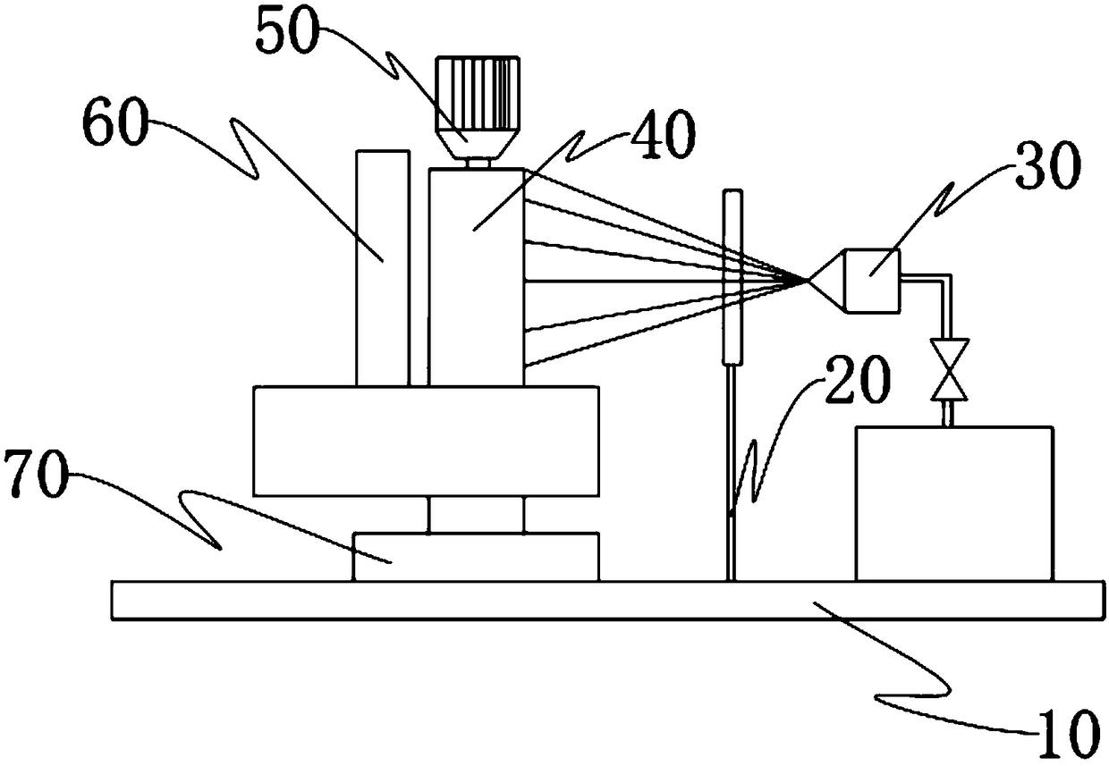
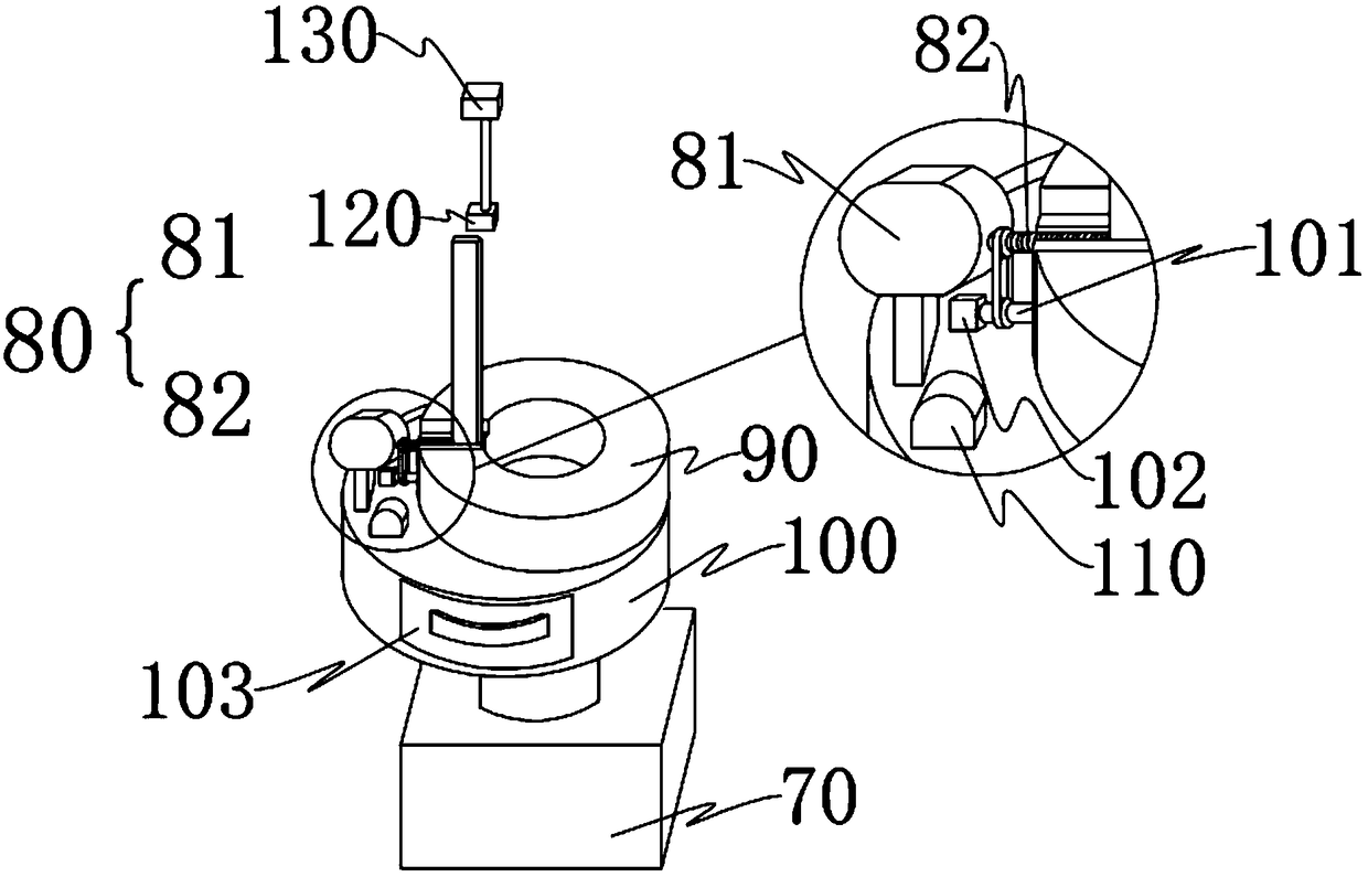
[0020] exist figure 1 and figure 2 Shown is an embodiment of a spray paint collection device of the present invention, the device includes a base 10, a positioning part 20 fixed on the base 10 for supporting workpieces, a spray gun 30 and a rotating part 40 located on both sides of the positioning part 20 , also includes a first driving device 50 located above the rotating member 40 to drive the rotating member 40 to rotate, a cutter 60 located on one side of the rota...


PUM


Abstract

The invention provides a spray paint collecting device. The spray paint collecting device comprises a base, a positioning part fixed to the base and used for supporting a workpiece, a spray gun and a rotating part, wherein the spray gun and the rotating part are located on the two sides of the positioning part. The spray paint collecting device further comprises a first driving device located above the rotating part and driving the rotating part to rotate, a cutter which is located on one side of the rotating part and is parallel to and aligned with the axial direction of the surface of the rotating part, a second driving device fixed below the cutter and controlling the cutter to rotate around the rotating part, and a third driving mechanism rotating in the radial direction of the rotating part. By means of the above technical scheme, compared with the prior art, disengaging of paint on the rotating part can be thoroughly conducted through the spray paint collecting device, in addition, due to the fact that the cutter is exposed, the cutter is more conveniently and more simply cleaned, and practicability and operability of the device are improved; and the production efficiency is improved, and the labor cost is saved.

Description

technical field [0001] The invention relates to a metal piece painting tool, in particular to a painting collecting device. Background technique [0002] When spraying paint on the surface of the bow and arrow, due to the influence of the spray gun flow and the shape of the workpiece, overspray often occurs, that is, the paint is sprayed to the outside of the workpiece, resulting in a large amount of waste of paint. Although the oversprayed paint can be recycled after painting, this method is labor-intensive and takes a lot of time, which increases the cost of painting. In order to solve the above problems, there is a technical solution such as that described in the 201510670548.1 patent in the prior art, that is, rotating parts and spray guns are arranged on both sides of the workpiece, and when overspray occurs, the oversprayed paint is collected on the rotating parts , when the paint accumulates to a certain thickness, the driving device can scrape off the paint on the r...

Claims


Application Information

Patent Timeline
Patent Type & Authority Patents(China)
IPC IPC(8): B05B14/00B05B15/50B05B13/02
CPCB05B13/0228B05B14/00
Inventor 方焕彬
Owner 浩锐星宸天津科技有限公司
Why Eureka
Try Eureka