Interlocking mechanism for drawer of low-voltage switch cabinet

A technology for low-voltage switch cabinets and drawers, which is applied in the direction of pull-out switch cabinets, switchgear, electrical components, etc., and can solve the problems of opening drawers, not installing interlock mechanisms, and prone to safety accidents

Inactive Publication Date: 2017-08-04
安徽捷胜五金电气设备制造有限公司
View PDF4 Cites 5 Cited by
  • Summary
  • Abstract
  • Description
  • Claims
  • Application Information

AI Technical Summary

Problems solved by technology

There are multiple drawers inside the low-voltage switchgear, but the drawers of the low-voltage switchgear are not equipped with an interlock mechanism. When the low-voltage switch is charged, the drawer will be opened due to misoperation, which is prone to safety accidents

Method used


Image

  • Interlocking mechanism for drawer of low-voltage switch cabinet
  • Interlocking mechanism for drawer of low-voltage switch cabinet
  • Interlocking mechanism for drawer of low-voltage switch cabinet

Examples


Embodiment Construction

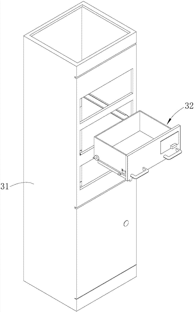
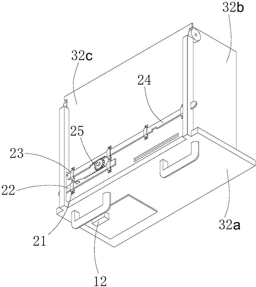
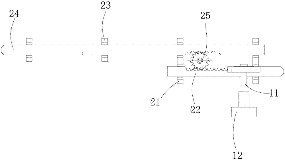
[0021] Such as Figures 1 to 4 shown

[0022] The chain mechanism includes a toggle component and a pin component.

[0023] The toggle assembly includes a rotating shaft 11 , a driving gear 13 , a reed 15 and a lever 14 .

[0024] The rotating shaft 11 runs through the panel 32a of the low-voltage switch cabinet drawer 32 horizontally, and one end of the rotating shaft 11 extends out of the panel 32a of the low-voltage switch cabinet drawer 32, and the end of the rotating shaft 11 protruding out of the low-voltage switch cabinet drawer 32 panel 32a is fixed with a switch handle 12, The rotating shaft 11 is supported on the panel 32a of the drawer 32 of the low-voltage switchgear through the switch handle 12. The driving gear 13 is fixedly installed on the rotating shaft 11. The driving gear 13 is located in the drawer 32 of the low-voltage switchgear. On the panel 32a of the cabinet drawer 32, the upper end of the driving lever 14 is provided with teeth that cooperate with t...


PUM


Abstract

The present invention provides an interlocking mechanism for the drawer of a low-voltage switch cabinet. The interlocking mechanism comprises a poking assembly and a pin lock assembly. The rotating shaft of the poking assembly is supported on a panel of a drawer of a low-voltage switch cabinet. One end of the rotating shaft extends out of the panel of the drawer of the low-voltage switch cabinet. A driving gear is fixedly arranged on the rotating shaft. The end portion of one side of a poking rod is provided with teeth matched with the driving gear. A first sliding channel of the pin lock assembly is arranged on the bottom plate of the drawer of the low-voltage switch cabinet. A driving pin can slide along the first sliding channel to extend out of the side of the drawer of the low-voltage switch cabinet and is matched with the side wall of the low-voltage switch cabinet. The driving pin is provided with a poking hole. The end portion of the poking rod of the poking assembly, away from the direction of the driving gear, extends into the poking hole. The rotating shaft of the poking assembly drives the driving gear to rotate, and then the poking rod drives the driving pin to extend out or retract back along the direction of the first sliding channel. Therefore, the drawer of the low-voltage switch cabinet is kept in the dead-locked or freely movable state.

Description

technical field [0001] The invention relates to an interlocking mechanism, in particular to an interlocking mechanism for a drawer of a low-voltage switch cabinet. Background technique [0002] Low-voltage complete switchgear and control equipment are commonly known as low-voltage switchgear, also known as low-voltage power distribution cabinets, which refer to complete sets of electrical devices with AC and DC voltages below 1000V. Low-voltage switchgear is widely used in smart grid, infrastructure construction and implementation, and manufacturing fields. There are multiple drawers inside the low-voltage switchgear, but the drawers of the low-voltage switchgear are not equipped with an interlock mechanism. When the low-voltage switch is charged, the drawer will be opened due to misoperation, which is prone to safety accidents. Contents of the invention [0003] The technical problem to be solved by the present invention is to provide a simple in structure and easy to us...

Claims


Application Information

Patent Timeline
Patent Type & Authority Applications(China)
IPC IPC(8): H02B11/133H02B11/173
CPCH02B11/133H02B11/173
Inventor 刘明坤
Owner 安徽捷胜五金电气设备制造有限公司
Why Eureka
Try Eureka