
Hybrid power tractor braking system with retarder and control method of hybrid power tractor brake system

A hybrid power and retarding braking technology, which is applied in electric braking systems, brakes, electric vehicles, etc., can solve the problems of no braking energy recovery function, no mature resources, and large energy-consuming devices, so as to improve the overall vehicle performance. Economical, ensure the drivability of the whole vehicle, and improve the life of the retarder

Pending Publication Date: 2017-08-04
CHINA FIRST AUTOMOBILE
View PDF7 Cites 10 Cited by
  • Summary
  • Abstract
  • Description
  • Claims
  • Application Information

AI Technical Summary

Problems solved by technology

[0008] However, what is mentioned in Patent Document 1 is a hybrid system without a traditional retarder, and the motor of the hybrid system is used to realize the function of the traditional retarder, but the energy-consuming device mentioned is relatively large, and the Without mature resources, the actual product application is difficult
Patent Document 2 refers to a retarder, which uses the retarder to realize the braking recovery function. It is difficult to improve the traditional eddy current retarder, and it is difficult to apply the actual product.
Patent Document 3 is essentially an improvement on the braking system of a traditional vehicle. Through the joint action of the retarder and the traditional air pressure brake, it meets the braking requirements of the entire vehicle. It has nothing to do with the hybrid power system, and there is no braking energy recovery. Function

Method used


Image

  • Hybrid power tractor braking system with retarder and control method of hybrid power tractor brake system
  • Hybrid power tractor braking system with retarder and control method of hybrid power tractor brake system
  • Hybrid power tractor braking system with retarder and control method of hybrid power tractor brake system

Examples


Embodiment Construction

[0032] In order to make the technical problems, technical solutions and advantages to be solved by the present invention clearer, the following will describe in detail with reference to the drawings and specific embodiments.

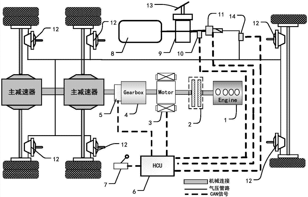
[0033] figure 1 A structural schematic diagram of a braking system of a hybrid tractor with a retarder provided by an embodiment of the present invention. figure 2 A structural schematic diagram of a braking system of a hybrid tractor with a retarder provided in another embodiment of the present invention.

[0034] First, combine figure 1 A retarder-equipped braking system for a hybrid tractor according to a first embodiment of the present invention will be described.

[0035] Such as figure 1 As shown, the braking system of a hybrid tractor with retarder in the first embodiment of the present invention includes an engine 1, a clutch 2, a motor 3, a speed changer 4, a retarder 5, Retarder handle 7, hybrid controller (HCU) 6, air reservoir 8, brake v...


PUM


Abstract

The invention discloses a hybrid power tractor brake system with a retarder. The hybrid power tractor brake system with the retarder comprises an engine, a clutch, a motor, a transmission, a retarder, a retarder handle, a hybrid power controller, an air cylinder, a brake valve, a first gas pressure sensor, a second gas pressure sensor, an electric valve, a brake chamber and a brake pedal which are arranged on a tractor, wherein the engine is connected with the motor through the clutch, the motor is connected with the transmission, the transmission is in serious with the retarder, the brake pedal is connected with the brake valve, the air cylinder , the brake valve, the electric valve and the brake chamber are sequentially connected through a pneumatic pipeline, the first gas pressure sensor is mounted in the pneumatic pipeline at the rear of the brake valve , and the second gas pressure sensor is mounted in the pneumatic pipeline at the rear of the electric valve. The invention further discloses a control method of the hybrid power tractor brake system. The hybrid power tractor brake system can recycle brake energy as much as possible while meeting brake requirements of a driver, and thus oil consumption of the whole tractor is reduced.

Description

technical field [0001] The invention relates to a brake system of a tractor, in particular to a brake system of a hybrid tractor with a retarder and a control method thereof, and belongs to the technical field of tractor brake systems. Background technique [0002] At present, with the development of the trend of electrification of automobiles, major domestic and foreign automobile manufacturers have also begun to carry out electrification research on tractors. For example, foreign companies such as MAN and DAF have developed hybrid tractors, which claim fuel-saving rate Between 4% and 8%, domestic Dongfeng is also conducting research and development of P2 hybrid tractors. The hybrid system includes components such as engine, drive motor, transmission and battery. It is realized by the braking energy recovery function, that is, the motor generates electricity during braking and stores the electric energy in the battery, and the power of the battery is provided to the motor f...

Claims


Application Information

Patent Timeline
IPC IPC(8): B60L7/26B60T13/66
CPCB60T13/66B60L7/26Y02T90/16
Inventor 刘建康李川杨兴旺
Owner CHINA FIRST AUTOMOBILE
Learn More