Punching concave mold edge structure

A technology of die and cutting edge, which is applied in the field of punching die cutting edge structure, can solve problems such as bad indentation of stamping parts, accidents of lamination touching the cutting edge, etc., and achieve the effect of solving the problem of rebound

Inactive Publication Date: 2017-08-04
农思宇
View PDF9 Cites 0 Cited by
  • Summary
  • Abstract
  • Description
  • Claims
  • Application Information

AI Technical Summary

Problems solved by technology

[0002] The punching waste from high-speed stamping bounces back to the surface of the die, which will cause bad indentations on the stamping parts, or cause edge collision accidents in laminate stamping

Method used


Image

  • Punching concave mold edge structure

Examples


Embodiment Construction

[0009] The present invention will be further described now in conjunction with accompanying drawing. These drawings are all simplified schematic diagrams, which only illustrate the basic structure of the present invention in a schematic manner, so they only show the configurations related to the present invention.

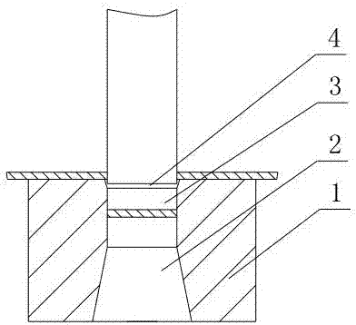
[0010] Such as figure 1 The shown cutting edge structure of a punching die includes a die body 1, and the die body 1 is provided with a die through hole that runs through the upper surface of the die body 1 and the lower surface of the die body 1, and the die through hole Including the lower discharge conical hole 2 and the cylindrical hole 3, the through hole of the die also includes the conical hole 4 arranged between the cylindrical hole 3 and the upper surface of the die body 1, and the two ends of the cylindrical hole 3 are connected with the lower discharge conical hole 2 respectively. The small hole ends of the conical hole 4 are connected, the depth of the...


PUM

PropertyMeasurementUnit
depthaaaaaaaaaa

Abstract

The invention discloses a punching concave mold edge structure. The punching concave mold edge structure comprises a concave mold body; a concave mold through hole for penetrating through the upper surface and the lower surface of the concave mold body is formed in the concave mold body; the concave mold through hole includes a lower discharge conical hole and a cylindrical hole; the concave mold through hole further includes a conical hole formed between the cylindrical hole and the upper surface of the concave mold body; two ends of the cylindrical hole respectively communicate with small hole ends of the lower discharge conical hole and the conical hole; the depth of the conical hole is 1 mm; the conical vertex angle of the conical hole is 1-2 degrees; and the conical vertex angle of the lower discharge conical hole is 4-6 degrees.

Description

technical field [0001] The invention relates to a cutting edge structure of a punching die. Background technique [0002] The punching waste from high-speed stamping bounces back to the surface of the die, which will cause bad indentations on the stamping parts, or cause edge collision accidents in laminate stamping. The reasons for the rebound of the punching waste are: the waste is adhered by the oil film; the waste and the end face of the punch produce vacuum adsorption, etc. Contents of the invention [0003] The technical problem to be solved by the present invention is to overcome the deficiencies in the prior art and provide a cutting edge structure of the punching die which avoids punching waste from bouncing back. [0004] The technical solution adopted by the present invention to solve the technical problem is: a cutting edge structure of a punching die, including a die body, the die body is provided with a die through hole that runs through the upper surface of...

Claims


Application Information

Patent Timeline
Patent Type & Authority Applications(China)
IPC IPC(8): B21D28/34
CPCB21D28/34
Inventor 农思宇
Owner 农思宇
Why Eureka
Try Eureka