Impurity removal device for removing impurities from large-capacity gas flow

A technology of gas flow and large volume, which is applied in the natural gas chemical industry and petroleum fields, can solve the problems of not being able to meet the requirements of large volume, and achieve the effects of simple structure, slow flow speed, resource recycling, energy saving and consumption reduction

Pending Publication Date: 2017-08-04
克拉玛依市杰德科技有限责任公司
View PDF13 Cites 0 Cited by
  • Summary
  • Abstract
  • Description
  • Claims
  • Application Information

AI Technical Summary

Problems solved by technology

[0005] The existing method is to pass the tail gas into a sealed device, which contains liquid medicine, and the gas is mixed with the liquid medicine. After fully reacting, the harmful gas or impurities in the tail gas are removed. However, in the existing equipment and devices , unable to meet the requirements of the air volume, the air volume refers to the volume of gas that needs to remove impurities per unit time
[0006] For gas injection wells, the daily exhaust volume of a single well can reach hundreds of thousands of cubic meters, and the existing equipment cannot meet the needs. Therefore, a simple structure, ingenious design, good use effect, and satisfactory impurity removal effect device is proposed

Method used


Image

  • Impurity removal device for removing impurities from large-capacity gas flow
  • Impurity removal device for removing impurities from large-capacity gas flow
  • Impurity removal device for removing impurities from large-capacity gas flow

Examples


Embodiment 1

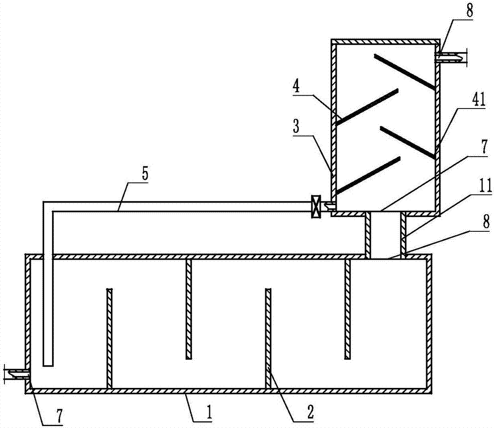
[0035] Embodiment 1: refer to figure 1 , is a structural schematic diagram of Embodiment 1 of the present invention, and is provided with a group of horizontal tank body 1 and a group of vertical tank body 3, and the horizontal tank body 1 and the vertical tank body 3 are all provided with an air inlet 7 and Gas outlet 8, a return pipe 5 and a connecting pipe 11 are arranged between the horizontal tank body 1 and the vertical tank body 3, one end of the connecting pipe 11 is connected to the gas outlet 8 of the horizontal tank body 1, and the other end is connected to the vertical tank body 1 The horizontal tank body 3 is connected to the air inlet 7, and the horizontal tank body 1 is provided with four barrier plates A2, the barrier plates A2 are straight, and the adjacent barrier plates A2 are in the horizontal tank body 1 Arranged in such a way that the free ends are staggered, several barrier plates B4 are provided on the inner wall of the vertical tank body 3, and the bar...

Embodiment 2

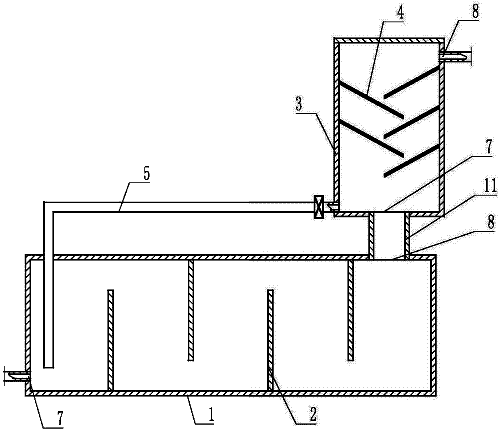
[0039] Embodiment 2: refer to figure 2 , is a schematic diagram of the structure of Embodiment 2 of the present invention. Compared with Embodiment 1, the difference of this embodiment is that the barrier plate B is arranged in the form of "\ / " on the inner wall of the vertical tank body 3.

Embodiment 3

[0040] Embodiment 3: refer to Figure 3-4 , is a structural schematic diagram of Embodiment 3 of the present invention. Compared with Embodiments 1 and 2, the difference of this embodiment is that a baffle 10 is provided inside the vertical tank body 3, and the baffle 10 is arranged on the air intake Between the port 7 and the blocking plate B4, the baffle plate 10 is fixed on the inner wall of the vertical tank body 3 by a fixing rod 12 .

[0041] The barrier plate A2 is arranged in a mixed manner of arc shape and straight plate shape.

[0042] The gas is passed into the horizontal tank body 1 through the air inlet 7, the horizontal tank body 1 is provided with a liquid medicine, and the horizontal tank body 1 is provided with a barrier plate A2, and the upper and lower relative settings of the barrier plate A2 hinder The relative flow velocity of the liquid, when the gas is introduced from the air inlet 7, the liquid medicine will not be squeezed out from the air outlet 8 d...


PUM


Abstract

The invention provides an impurity removal device for removing impurities from a large-capacity gas flow. The impurity removal device provided by the invention is characterized by comprising at least one group of horizontal type tank body and at least one group of vertical type tank body, wherein an air inlet and an air outlet are formed in the horizontal type tank body and the vertical type tank body respectively, a return pipe and a connecting pipe are arranged between the horizontal type tank body and the vertical type tank body, one end of the connecting pipe is connected with the air outlet of the horizontal type tank body, the other end of the connecting pipe is connected with the air inlet of the vertical type tank body, a plurality of separating plates A are arranged in the horizontal type tank body, each separating plate A is a platy body, one end of each separating plate A is fixed on the inner wall of the horizontal type tank body, the other end of each separating plate A is a free end, a plurality of separating plates B are arranged on the inner wall of the vertical type tank body, each separating plate B is a platy body, one end of each separating plate B is fixed on the inner wall of the vertical type tank body, and the other end of each separating plate B is a free end. The impurity removal device provided by the invention has the characteristics of simple structure, high impurity removal efficiency, cyclic utilization of resources, energy conservation and consumption reduction.

Description

technical field [0001] The invention relates to the field of petroleum and natural gas chemical industry, in particular to an impurity removal device for removing impurities from a large gas flow. Background technique [0002] In the process of oil field development, the selection of oil recovery method plays an important role in exerting oil well productivity, improving recovery efficiency and reducing production cost. For different types of crude oil and oil layers with different geological characteristics, there are various oil recovery methods, such as water injection, gas injection, and oil layer fire. [0003] The burning oil layer method is also called the fire flooding method, which is a thermal oil recovery method in which the oil layer itself generates heat. Burning the oil layer is to inject some form of oxidant (air or oxygen) into the oil layer to make the oil in it ignite naturally, and then the injected oxidant will expand in the oil reservoir to form a combu...

Claims


Application Information

Patent Timeline
IPC IPC(8): B01D53/78B01D53/52B01D53/96B01D45/08
CPCB01D45/08B01D53/52B01D53/78B01D53/96B01D2258/02
Inventor 卜振民丁湘华程阳崔喜江郭晓璐刘民
Owner 克拉玛依市杰德科技有限责任公司
Why Eureka
Try Eureka