
Interference detection

A technology that interferes with devices and wireless access points. It is applied in the field of wireless communication and can solve problems such as Wi-Fi link damage, Wi-Fi transmitters being unable to perceive channels, and Wi-Fi range reduction.

Active Publication Date: 2017-08-01
BRITISH TELECOMM PLC
View PDF5 Cites 2 Cited by
  • Summary
  • Abstract
  • Description
  • Claims
  • Application Information

AI Technical Summary

Problems solved by technology

For some Wi-Fi receivers with poor out-of-band rejection (especially older hardware that was released when the surrounding spectrum was largely unused), LTE transmissions in these bands can lead to relatively low performance impacts on Wi-Fi throughput. adjacent channel interference
The main impact is to cause a reduction in the sensitivity of the Wi-Fi receiver, resulting in reduced Wi-Fi range and reduced throughput within range
In worse cases, i.e., where the LTE transmit power is high (eg, >15dBm) and the LTE transmitter is close to the Wi-Fi site (eg, <1m), the LTE transmission can raise the noise floor above the carrier detection level. A listening threshold such that the Wi-Fi transmitter cannot sense that the channel is idle, and thus never transmit, which can lead to the destruction of the Wi-Fi link and possible disconnection

Method used


Image

  • Interference detection
  • Interference detection
  • Interference detection

Examples


Embodiment approach

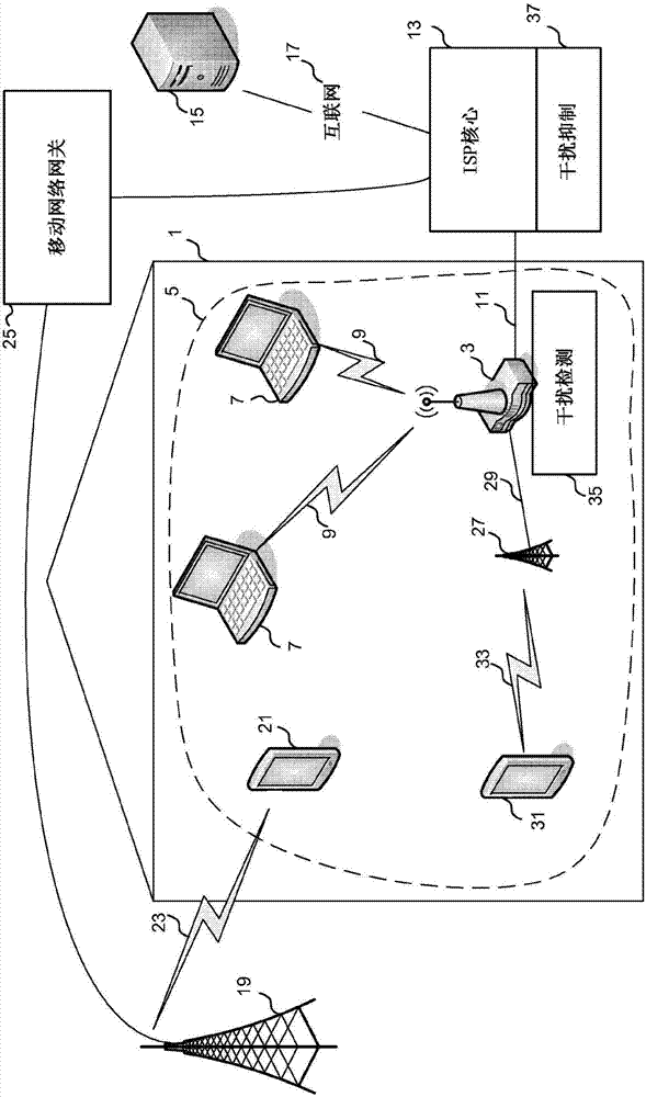
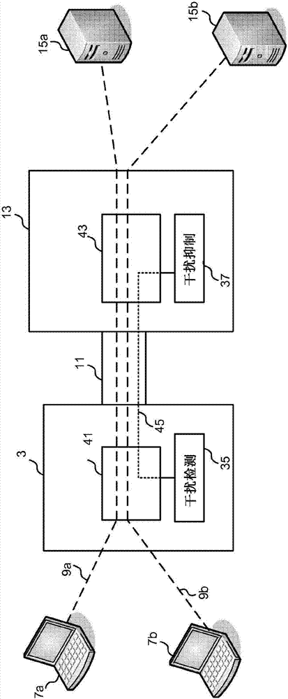
[0064] According to a first embodiment, the interference detection function 35 is configured to monitor the devices connected to the hub 3 and in particular to monitor the data flow carried by the hub 3 between the devices.

[0065] Such as Figure 5 As shown in , with the addition of an LTE femtocell 27 connected to the mobile network gateway 25, the interference detection component 35 will determine that there is a new data stream 47 carried by the hub.

[0066] Interference detection component 35 then compares the list of all flows to the matching criteria. Examples of matching criteria may include the MAC address of a known LTE femto cell or the IP address of a known mobile network gateway.

[0067] exist Figure 5 , the flow attributes of flow 47 match, and thus interference detection component 35 can identify LTE femtocell 27 (which is the device corresponding to the local IP address of flow 47) as a target for a Wi-Fi device also connected to hub 3 potential source o...

no. 2 approach

[0168] In a first embodiment, the interference detection component is configured to detect the presence of any potentially interfering devices connected to the hub, and the interference suppression component determines an appropriate response to suppress the interference. In the event that the hub is not connected to any interfering devices, the hub will not report any interfering devices to the interference management component.

[0169] Figure 12 An example network system in the second embodiment is shown.

[0170] exist Figure 12 In a network of , several hubs 201a - 201f are shown with wireless access points 203 to create a wireless LAN 205 . Some of the hubs 201a, 201b, 201e also have small cells 207 attached to them. For example, a first hub 201a has a femtocell 207a, a second hub 201b has a femtocell 207b, and a third hub 201e has a picocell 207c.

[0171] Each hub 201 performs processing according to the first embodiment to inform the interference suppression com...

no. 3 approach

[0216] In a third embodiment, the interference mitigation component is located within the network core and is configured to perform hub processing on connected hubs as in the first embodiment, but also operates to detect hubs that may be affected by small cells of neighboring hubs . The interference suppression component includes additional processing to determine the geographic location of the connected hubs, and applies aggregation processing of the connected hub interference information so that suppression information can be sent to a cluster of neighboring hubs.

[0217] Figure 15 The outline of the network system in the third embodiment is shown.

[0218] exist Figure 15 in the network (with Figure 12 Similar to the network of the second embodiment shown in ), multiple hubs 301a-301f are shown with wireless access points 303 to create a wireless LAN 305. Some of the hubs 301a, 301b, 301e also have small cells 307 attached to them. For example, a first hub 301a has...


PUM


Abstract

Wireless access point devices having wireless networks operating in accordance with 802.11b / g 2.4Ghz Wi-Fi can be affected by out-of-band interference caused by LTE small cell devices such as macrocells and femtocells. The wireless access points detect such interference devices using a flow processor to monitor the characteristics of data flows of devices connected to the wireless access point to determine whether they are LTE cells based on MAC address matching or the termination of a flow at a known mobile network operator gateway. When a cell is detected, the wireless access point scans for neighbouring wireless networks of neighbouring wireless access points which may also be affected by the interference generated by the LTE cell. A management server processes information relating the LTE cell and the neighbouring wireless networks and generates a mitigation action to change the operational behaviour of the wireless access point and any neighbouring wireless access points to mitigate the effect of the detected interference device on the wireless networks.

Description

[0001] The present invention relates to wireless communications, and in particular, to methods and apparatus for detecting the presence of potential sources of interference and taking countermeasures. Background technique [0002] In wireless communications, the IEEE 802.11 family of standards related to "Wi-Fi" is now a popular system that allows devices to communicate wirelessly using radio wave transmission. A cluster of devices all communicating via a common wireless access gateway is called a wireless local area network (WLAN). [0003] Wi-Fi communication is licensed to work in two frequency bands 2.4Ghz and 5Ghz in the radio spectrum. Currently, most devices are only able to work in the popular 2.4Ghz spectrum band, while more newer devices also work in the generally less crowded 5Ghz band. [0004] In 2.4Ghz Wi-Fi, the spectrum between 2402Mhz and 2472Mhz is divided into several channels, each channel has a center frequency that is 5Mhz apart from its neighbors. Howe...

Claims


Application Information

Patent Timeline
Patent Type & Authority Applications(China)
IPC IPC(8): H04J11/00H04W4/70
CPCH04J11/0023H04W4/70H04L2101/622H04J11/005H04W84/042H04W84/12H04W88/16H04L41/0813H04W24/08H04W88/08H04L41/0816H04W8/005H04W8/26H04W24/02H04W28/0236H04W28/04H04W52/241
Inventor F·斯卡希尔S·林兰德D·汤恩德R·埃文登
Owner BRITISH TELECOMM PLC
Learn More