Horizontal blind

A shutter and horizontal technology, which is applied in the field of horizontal shutters, can solve the problems of increased resistance, jamming, and non-smoothness of lifting ropes and blades, and achieve the effect of improving the descending performance

Inactive Publication Date: 2017-08-01
TACHIKAWA
View PDF5 Cites 0 Cited by
  • Summary
  • Abstract
  • Description
  • Claims
  • Application Information

AI Technical Summary

Problems solved by technology

[0009] In the horizontal blind of Patent Document 1, the lifting cords are bent and hung down in the front and rear directions of the blades, and especially when the blades are lowered, the resistance due to friction between the lifting wires and the blades becomes large, which may cause accidents. Smooth and stuck situations, so there is room for improvement especially in the descent performance of the blades
[0010] For example, in the case of blades made of hard materials such as wood, when the blades are lowered, the frictional resistance between the lifting rope and the blades becomes larger, and it is easy to cause roughness and jamming.
[0011] In addition, in the horizontal blind of Patent Document 1, a notch is provided on each vane, and the lifting cord is engaged with the notch to hang down. There may also be resistance due to friction

Method used


Image

  • Horizontal blind
  • Horizontal blind
  • Horizontal blind

Examples


Embodiment 1

[0060] (the blade of embodiment 1)

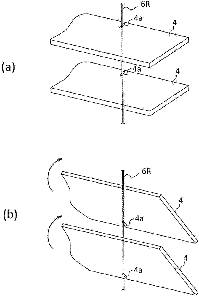
[0061] Figure 4 (a), (b) are the partial plan view and sectional drawing which demonstrated the shape of the long hole shape insertion hole 4a of the vane|blade 4 of Example 1 in the horizontal blind of this embodiment. in addition, Figure 4 (c) is a partial side sectional view explaining the state when the lift cord 6L (or 6R) hangs down with respect to the blade 4 of Example 1. FIG.

[0062] Such as Figure 4 As shown in (c), in the blade 4 of Embodiment 1, the following configuration example is shown: that is, the position where the lifting cord 6L (or 6R) inserted into the insertion hole 4a hangs down from the winding shaft 11 is smaller than the When the insertion hole 4a is located substantially on the indoor side, the lifting cord 6L (or 6R) is brought into contact with the outdoor side guide surface of the diverting pulley 13L (or 13R) provided below the winding shaft 11 to hang down.

[0063] In order to improve the descendin...

Embodiment 2

[0066] (the blade of embodiment 2)

[0067] Figure 6 (a), (b) is a partial plan view and sectional drawing which demonstrate the shape of the long hole shape insertion hole 4a of the vane|blade 4 of Example 2 in the horizontal blind of this embodiment. in addition, Figure 6 (c) is a partial side sectional view explaining the state when the lift cord 6L (or 6R) hangs down with respect to the blade 4 of Example 2.

[0068] Such as Figure 6 As shown in (c), in the blade 4 of the second embodiment, the following configuration example is shown: that is, the position where the lifting cord 6L (or 6R) inserted into the insertion hole 4a hangs down from the winding shaft 11 is smaller than the When the insertion hole 4a is located substantially outside the room, the lifting cord 6L (or 6R) is brought into contact with the indoor side guide surface of the diverting pulley 13L (or 13R) provided below the winding shaft 11 to hang down.

[0069] Such as Figure 6 As shown in (b) a...


PUM


Abstract

Provided is a horizontal blind configured so that a plurality of tiers of slats suspended and supported by ladder cords are lifted and lowered using a plurality of lifting and lowering cords. The horizontal blind comprises: pairs of ladder cords (7L, 7M, 7R) arranged and suspended at a plurality of locations in the longitudinal direction of a head box (1); a plurality of tiers of slats (4) each supported by horizontal threads (7a, 7b) connected between a pair of ladder cords 7L (or 7M or 7R) at a predetermined distance from each other; and a plurality of lifting and lowering cords (6L, 6M, 6R) suspended from the head box (1) at positions near the pair of ladder cords 7L (or 7M or 7R). The lifting and lowering cords 6L, 6R at the opposite ends of each of the slats (4) are passed and suspended through insertion holes 4a (or cutouts 4b) which are provided either at the center of the slat (4) in the transverse direction thereof or near an edge of the slat (4) in the transverse direction thereof, the edge facing the outside of the room. The insertion holes 4a (or cutouts 4b) are tapered in the depth direction thereof.

Description

technical field [0001] The invention relates to a horizontal blind which uses a plurality of hoisting ropes to raise or lower multilayer blades suspended and supported by direction control ropes. Background technique [0002] In the horizontal blinds, multiple lifting ropes can be used to raise or lower the multi-layer blades supported by the direction control ropes suspended from the upper beam, and then the blades can be tilted by operating the direction control ropes, so that the injection can be adjusted. The amount of sunlight in the room. [0003] For example, a lower beam is arranged at the lower end of the direction control rope, and the lower beam can be raised and lowered by introducing the lifting rope attached to the lower beam into the upper beam and pulling out the lifting rope from the upper beam. blade. [0004] As such a horizontal blind, there is disclosed a configuration in which lift cords are bent and hung down at respective edges in the front-rear dir...

Claims


Application Information

Patent Timeline
Patent Type & Authority Applications(China)
IPC IPC(8): E06B9/384E06B9/303
CPCE06B9/303E06B9/384
Inventor 植松贵俊
Owner TACHIKAWA
Why Eureka
Try Eureka