
Bearing device for changing supporting force of steel framework of deep foundation pit according to soil covering amount

A load-bearing device and support device technology, which is applied in infrastructure engineering, construction, excavation, etc., can solve the problems of reducing the service life of steel skeletons, bearing loads, and increasing the strength of steel skeletons, so as to ensure normal use, ensure safety, The effect of improving the ability to undertake

Active Publication Date: 2022-03-18
THE FOURTH ENGIENERING OF CHINA RAILWAY18 BUREAU GROUP +1
View PDF10 Cites 0 Cited by
  • Summary
  • Abstract
  • Description
  • Claims
  • Application Information

AI Technical Summary

Problems solved by technology

[0002] Deep foundation pit refers to a project whose excavation depth exceeds 5 meters or the depth does not exceed 5 meters, but the geological conditions, surrounding environment and underground pipelines are particularly complicated. In deep foundation pits, steel skeletons are often built as support pits or work Platform, when working in a deep foundation pit, the soil on the foundation pit can easily fall on the steel frame to increase the bearing strength of the steel frame. When too much soil accumulates on the steel frame, it is easy to make the steel frame built The middle part of the frame bears heavy loads, which reduces the service life of the steel frame and increases the danger of workers working on the steel frame

Method used


Image

  • Bearing device for changing supporting force of steel framework of deep foundation pit according to soil covering amount
  • Bearing device for changing supporting force of steel framework of deep foundation pit according to soil covering amount
  • Bearing device for changing supporting force of steel framework of deep foundation pit according to soil covering amount

Examples


Embodiment 1

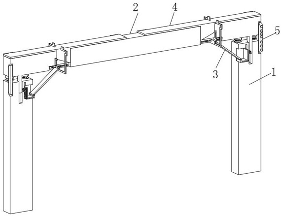
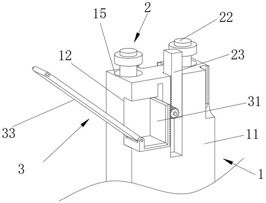
[0038] see Figure 1-Figure 10 As shown, the purpose of this embodiment is to provide a load-bearing device for changing the supporting force of the deep foundation pit steel skeleton according to the amount of soil covering, including two supporting devices 1 and a crossbeam 2 arranged at the upper ends of the two supporting devices 1, and the supporting device 1 1. The position where the crossbeam 2 is connected is provided with a load-bearing mechanism 3 for supporting the crossbeam 2. The support device 1 includes a support column 11. The four corners of the upper end of the support column 11 are provided with plug holes 15. The crossbeam 2 includes a crossbeam rod 21 and is fixed on the crossbeam rod. 21 several plug-in posts 22 at the bottom of both ends, a spring stop ring 26 is fixed on the plug-in post 22, an anti-compression spring 29 with one end fixed on the spring stop ring 26 is sleeved on the plug-in post 22, and the anti-compression spring 29 One end of the spr...


PUM


Abstract

The invention relates to the technical field of steel skeleton supporting, in particular to a bearing device for changing the supporting force of a steel skeleton of a deep foundation pit according to the soil covering amount. The device comprises two supporting devices and a cross beam arranged at the upper ends of the two supporting devices, a bearing mechanism used for supporting the cross beam is arranged at the connecting position of the supporting devices and the cross beam, each supporting device comprises a supporting column, inserting holes are formed in the four corners of the upper end of each supporting column, and the cross beam comprises a cross beam rod and a plurality of inserting columns fixed to the bottoms of the two ends of the cross beam rod; and a spring baffle ring is fixed on the inserting column. The bearing mechanism is used for bearing a cross beam for bearing soil, after the cross beam bears the soil, the cross beam moves downwards, a driving toothed plate drives a gear, the gear drives a positioning sliding plate to move upwards, the moving positioning sliding plate drives one end of the positioning sliding plate to move upwards, and the other end of a supporting rod changes the supporting position of a cross beam rod; the supporting rod supports the middle of the cross beam rod, and the bearing capacity of the cross beam rod to soil is improved.

Description

technical field [0001] The invention relates to the technical field of steel frame support, in particular to a load-bearing device for changing the support force of a deep foundation pit steel frame according to the amount of soil covering. Background technique [0002] Deep foundation pit refers to a project whose excavation depth exceeds 5 meters or the depth does not exceed 5 meters, but the geological conditions, surrounding environment and underground pipelines are particularly complicated. In deep foundation pits, steel skeletons are often built as support pits or work Platform, when working in a deep foundation pit, the soil on the foundation pit can easily fall on the steel frame to increase the bearing strength of the steel frame. When too much soil accumulates on the steel frame, it is easy to make the steel frame built The middle part of the frame bears heavy loads, which reduces the service life of the steel frame and increases the danger of workers working on th...

Claims


Application Information

Patent Timeline
Patent Type & Authority Applications(China)
IPC IPC(8): E02D17/04E02D5/76
CPCE02D17/04E02D5/765
Inventor 万朝栋汪龙兵张建鹏祁小龙杨旺军樊金霖刘磊
Owner THE FOURTH ENGIENERING OF CHINA RAILWAY18 BUREAU GROUP
Learn More