
Pneumatic tire

A pneumatic tire, tire circumferential technology, applied to tire parts, tire tread/tread pattern, transportation and packaging, etc., to improve wear resistance, fully maintain wear resistance, and relieve stress concentration

Active Publication Date: 2017-08-01
THE YOKOHAMA RUBBER CO LTD
View PDF8 Cites 3 Cited by
  • Summary
  • Abstract
  • Description
  • Claims
  • Application Information

AI Technical Summary

Problems solved by technology

[0004] However, just by adjusting the shape, groove width, arrangement, etc. of the transverse grooves, it is not necessarily possible to achieve a high degree of both snow performance and wear resistance, and further improvement is required.

Method used


Image

  • Pneumatic tire
  • Pneumatic tire
  • Pneumatic tire

Examples


example

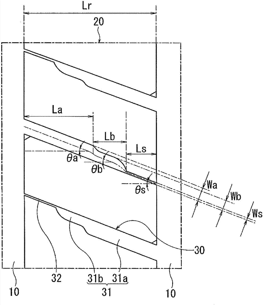
[0056] When the tire size is 215 / 60R16, with figure 1 The reinforcement structure exemplified in and except for the composite groove (and the circumferential auxiliary groove) are figure 2 In tires based on the tread pattern of , the structure of the composite groove, the ratio of the groove width of the composite groove (ratio Wa / Wb, ratio Wb / Ws), the ratio of groove length (ratio La / Lr, ratio Lb / Lr, ratio Ls / Lr), the presence or absence of circumferential narrow grooves, and the groove width of circumferential narrow grooves, 15 kinds of pneumatic tires including Conventional Example 1, Comparative Examples 1 to 3, and Examples 1 to 11.

[0057] In these 15 kinds of pneumatic tires, except for Conventional Example 1, Comparative Examples 1-2, and Example 4, the shape of the composite groove is common to image 3 the shape shown. That is, each composite groove includes a transverse groove whose one end communicates with the main groove on one side and the other end termin...


PUM


Abstract

Provided is a pneumatic tire capable of improving on-snow performance and anti-wear performance. A plurality of compound grooves 30 comprising horizontal grooves 31, one end of which connects to a principal groove 10 on one side thereof and the other end of which ends inside a rib 20, and further comprising sipes 32 extending from the other end of the horizontal grooves 31 to a principal groove 10 on the other side thereof, are formed at an interval from one another in the tire-circumferential direction in one or more rows of ribs 20 positioned inside a center region Ce. The compound grooves 30 are positioned in a manner such that the opening direction of the horizontal grooves 31 relative to the principal grooves 10 alternatingly reverses in the tire circumferential direction. A wide section 31a and a narrow section 31b are formed in each of the horizontal grooves 31. The ratio Wa / Wb of the groove width Wa of the wide section 31a to the groove width Wb of the narrow section 31b is in the range of 1.2-3.0, and the ratio Wb / Ws of the groove width Wb of the narrow section 31b to the groove width Ws of the sipes 32 is in the range of 1.2-5.0.

Description

technical field [0001] The present invention relates to a pneumatic tire, and more specifically, to a pneumatic tire capable of improving on-snow performance and wear resistance. Background technique [0002] In all-season pneumatic tires that are used throughout the year and are assumed to be used on dry roads, wet roads, and snowy roads, in addition to the usual dry performance and wet performance, snow performance (for example, performance on snowy roads) is also required. driving stability). In addition, since it can be used on various road surfaces as described above, wear resistance is also required for long-term use. [0003] As a method of improving on-snow performance, for example, it is conceivable to provide a large number of lateral grooves extending in the tire width direction to secure edge components. However, when many transverse grooves are provided, the rigidity of the land portion decreases, making it difficult to obtain excellent wear resistance. There...

Claims


Application Information

Patent Timeline
Patent Type & Authority Applications(China)
IPC IPC(8): B60C11/03B60C11/12
CPCB60C11/03B60C11/12B60C2011/1209B60C2011/0372B60C11/0309B60C2011/0365B60C11/1236
Inventor 山川贵弘
Owner THE YOKOHAMA RUBBER CO LTD
Learn More