
Camera module testing method based on lattice standard board

A test method and technology for camera modules, applied in image communication, TV, electrical components, etc., can solve the problems of target area change, time-consuming calculation process, and inconsistent camera module parameters.

Inactive Publication Date: 2017-08-01
NINGBO SUNNY OPOTECH CO LTD
View PDF6 Cites 3 Cited by
  • Summary
  • Abstract
  • Description
  • Claims
  • Application Information

AI Technical Summary

Problems solved by technology

Such a test process not only leads to a relatively large amount of calculation and a relatively time-consuming calculation process, but also it is difficult to guarantee the accuracy of these test items for the camera module.
In addition, due to errors in each camera module, such as the existence of inconsistent eccentricity, the parameters of each camera module are not completely consistent, and when these test items are executed on the camera module, grid-shaped standard plates will occur. Slight movement (such as horizontal movement, vertical movement, tilt movement, etc.) will cause the position of the grid-shaped standard plate in the image of the camera module to change. The target area of ​​the standard plate will also change, resulting in relatively low accuracy of the test results of the camera module obtained by this manual testing method in the prior art

Method used


Image

  • Camera module testing method based on lattice standard board
  • Camera module testing method based on lattice standard board
  • Camera module testing method based on lattice standard board

Examples


Embodiment Construction

[0029] The following description serves to disclose the present invention to enable those skilled in the art to carry out the present invention. The preferred embodiments described below are only examples, and those skilled in the art can devise other obvious variations. The basic principles of the present invention defined in the following description can be applied to other embodiments, variations, improvements, equivalents and other technical solutions without departing from the spirit and scope of the present invention.

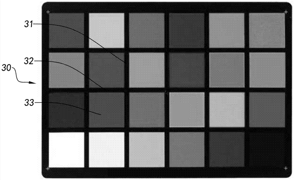
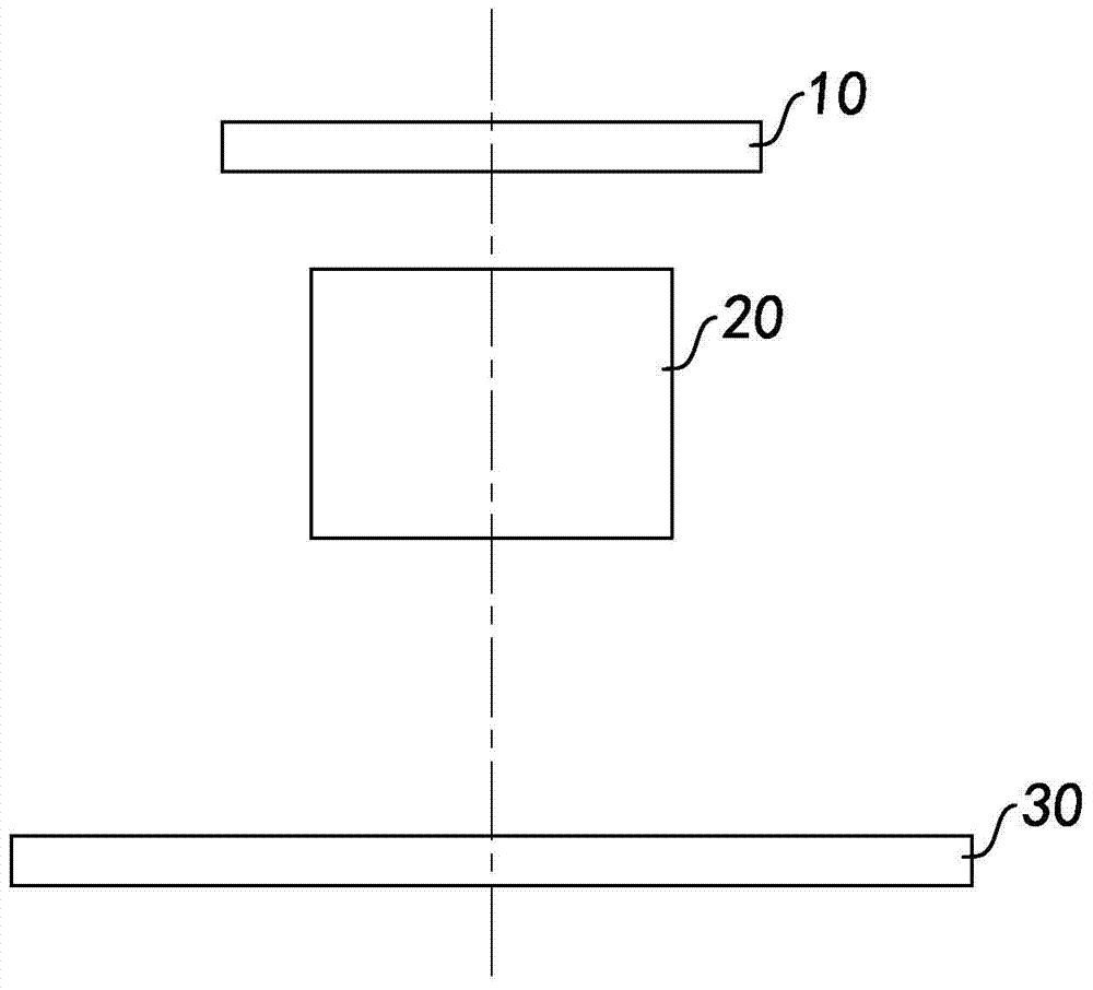
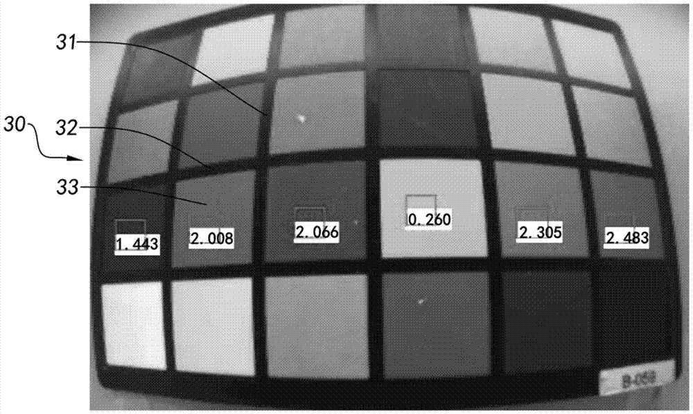
[0030] According to the accompanying drawings of the figure 1 and figure 2 According to a preferred embodiment of the present invention, the test method of the camera module based on the grid-shaped standard plate is illustrated, wherein the camera module includes a photosensitive chip 10 and a photosensitive path arranged on the photosensitive chip 10 An optical lens 20, the light reflected by the object can enter the inside of the camera module from ...


PUM


Abstract

The invention discloses a camera module testing method based on a lattice standard board. The testing method comprises the following steps: a database related to attributes of all intersection points in an image of the lattice standard board is provided; the camera module photographs the lattice standard board to acquire the image of the lattice standard board; all corner points in the image of the lattice standard board are captured; the attributes of the corner points and the attributes of the intersection points in the database are compared to determine positions of the corner points in the lattice standard board; and according to the positions of the corner points in the lattice standard board and the coordinates of the corner points, the coordinates of a target area are determined to calculate the value of the target area, and testing on the camera module is thus completed.

Description

technical field [0001] The invention relates to the field of testing of camera modules, in particular to a method for testing camera modules based on a grid-shaped standard plate. Background technique [0002] As a terminal for obtaining images, the camera module is one of the standard configurations of electronic devices such as mobile phones and tablet computers. In recent years, with the rapid advancement of the technology of these electronic devices and the popularity of these electronic devices in daily life, users have put forward more stringent requirements for the relevant parameters and functions of the camera module, the most typical is the user The camera modules that need to be configured on these electronic devices can provide them with higher quality images. This demand in the market first puts forward higher requirements for the manufacturing process of the camera module. [0003] During the manufacturing process of the camera module, performing a series of ...

Claims


Application Information

Patent Timeline
IPC IPC(8): H04N17/00
CPCH04N17/002
Inventor 杨盼郑杰
Owner NINGBO SUNNY OPOTECH CO LTD
Learn More