
Card locked pull-fall separation electrical connector

A technology of electrical connectors and locks, which is applied in the direction of connection and connection device components, circuits, etc., can solve the problems of easy jamming, large size, poor reliability, etc., and achieve easy pull-off and loose, simple and reliable operation , The effect of simple part structure

Inactive Publication Date: 2017-08-01
CHINA NORTH IND GRP HANGLIAN TECH CO LTD
View PDF6 Cites 5 Cited by
  • Summary
  • Abstract
  • Description
  • Claims
  • Application Information

AI Technical Summary

Problems solved by technology

[0002] Usually, the mating and separation of the connectors is performed manually. In some special occasions such as projectile launch, nuclear power and other fields, due to the harsh environmental conditions, personnel cannot approach the operation, and the electrical connectors that need to be automatically pulled off and separated are on the market. Fewer types of pull-off connectors are also available, such as the split nut type or the center lock sleeve type. The split nut type requires high precision in parts processing and assembly, otherwise it is easy to get stuck; while the center lock sleeve type has a slow mating speed and a large volume. Large, heavy, and unreliable

Method used


Image

  • Card locked pull-fall separation electrical connector
  • Card locked pull-fall separation electrical connector

Examples


Embodiment Construction

[0015] Further description will be made below in conjunction with drawings and embodiments.

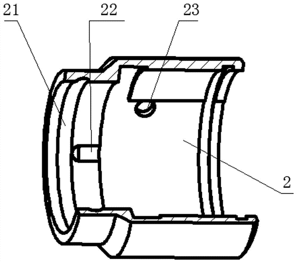
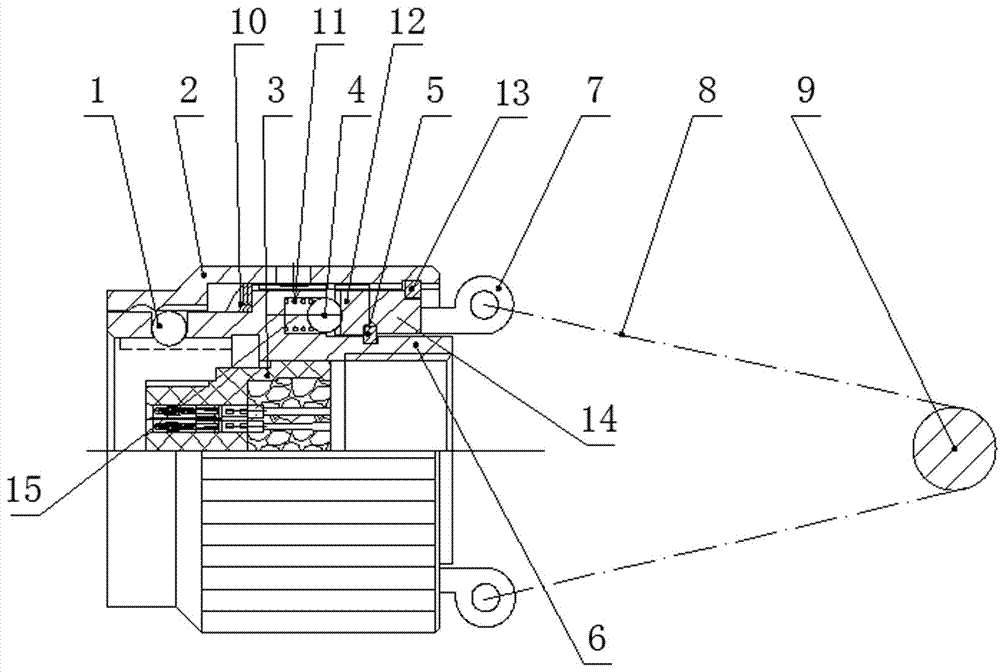
[0016] figure 1 , 2 Shown: a snap-lock type pull-off separation electrical connector includes a plug and a socket ( figure 2 not shown in ), the outer wall of the front part of the head shell 6 of the plug is provided with more than one locking steel ball 1 for locking the connection plug and socket, the hole core assembly 3 is arranged inside the head shell 6, and the locking sleeve 2 is socketed Outside the head housing 6, the locking sleeve is provided with a state identification 23 radially corresponding to the position mark on the head housing, and the inner wall of the front part of the locking sleeve 3 is provided with a circle of circumferential grooves 21 and more than one axial direction from outside to inside. Groove 22, the middle part of the inner wall of the locking sleeve 3 is elastically pressed against the front end of the outer wall of the head housing 6 via the c...


PUM


Abstract

The invention relates to a card locked pull-fall separation electrical connector. The electrical connector comprises a plug and a socket, wherein more than one locking steel ball is arranged on an outer wall of a front part of a head shell of the plug and is used for connecting the plug and the socket in a locking way, a hole core assembly is arranged in the head shell, the plug comprises a locking sleeve, a ripple spring, a springs, a steel ball, a ratchet, a positioning baffle ring, a pull ring connection sleeve, a connection sleeve baffle ring, a pull ring, a steel rope and a pull pin, the locking sleeve is sleeved outside the head shell, a circle of circumferential groove and more than one axial groove are formed in an inner wall of a front part of the locking sleeve from outside to inside, the inner wall of the locking sleeve elastically props against head shell through the ripple spring, the ratchet and the pull ring connection sleeve are connected with an inner wall of a rear part of the head shell through a spline from inside to outside, an inner end surface of the ratchet props against the head shell by a plurality of steel balls with the springs, an outer end surface of the ratchet is arranged at an upper limit of the head shell by the baffle ring, an outer end surface of the pull ring connection sleeve is limited by a connection sleeve baffle ring arranged on an inner wall of the locking sleeve, more than one upper pull ring is connected with the pull ring connection sleeve, and the pull ring is connected with the pull pin through a steel rope.

Description

technical field [0001] The invention relates to an electrical connector, in particular to a locking type pull-off separation electrical connector. Background technique [0002] Usually, the mating and separation of the connectors is performed manually. In some special occasions such as projectile launch, nuclear power and other fields, due to the harsh environmental conditions, personnel cannot approach the operation, and the electrical connectors that need to be automatically pulled off and separated are on the market. Fewer types of pull-off connectors are also available, such as the split nut type or the center lock sleeve type. The split nut type requires high precision in parts processing and assembly, otherwise it is easy to get stuck; while the center lock sleeve type has a slow mating speed and a large volume. Large, heavy, and unreliable. Contents of the invention [0003] In view of the above technical problems, the present invention provides an electrical conne...

Claims


Application Information

Patent Timeline
Patent Type & Authority Applications(China)
IPC IPC(8): H01R13/627
Inventor 叶学俊殷志根卢春兰蒋硕李竹法
Owner CHINA NORTH IND GRP HANGLIAN TECH CO LTD
Learn More