Fire cover for burner

A burner and fire cover technology, applied in the direction of burners, gas fuel burners, combustion methods, etc., can solve the problems of difficult cleaning, secondary air replenishment, low thermal efficiency, etc., achieve uniform annular heating, reduce separation, The effect of improving thermal efficiency

Pending Publication Date: 2017-07-28
VATTI CORP LTD
View PDF7 Cites 8 Cited by
  • Summary
  • Abstract
  • Description
  • Claims
  • Application Information

AI Technical Summary

Problems solved by technology

[0004] The fire holes of the existing atmospheric burner generally include: round fire holes, square fire holes, and strip-shaped fire holes. Both the round fire holes and the strip-shaped fire holes are machined. Dozens of fire holes are required on the fire cover, and there are problems such as low production efficiency, a large amount of material waste, and high processing costs; square fire holes are generally made by forging, but due to the large number of fire holes and tolerance requirements, the mold accuracy requirements High, complex mold and short life
[0005] In addition, the above-mentioned fire holes are all independent small holes, and there is still a pain point that it is not easy to clean after being blocked
[0006] A certain burner adopts annular flame holes, which solves the problem of high processing costs of round flame holes, square flame holes, and strip flame holes. The secondary air is difficult to replenish, and the technical defects of the flames between adjacent annular fire holes are easy to cross interference, which will cause problems such as yellow flames, unqualified CO content, and low thermal efficiency, and the structure also has the problem that stolen goods are easy to block the fire holes

Method used


Image

  • Fire cover for burner
  • Fire cover for burner
  • Fire cover for burner

Examples


Embodiment Construction

[0033] The features of the present invention and other relevant features will be described in further detail below through embodiments in conjunction with the accompanying drawings, so as to facilitate the understanding of those skilled in the art.

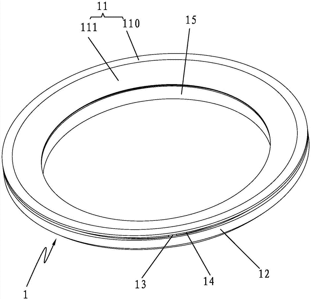
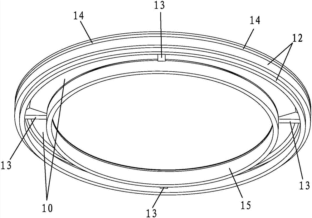
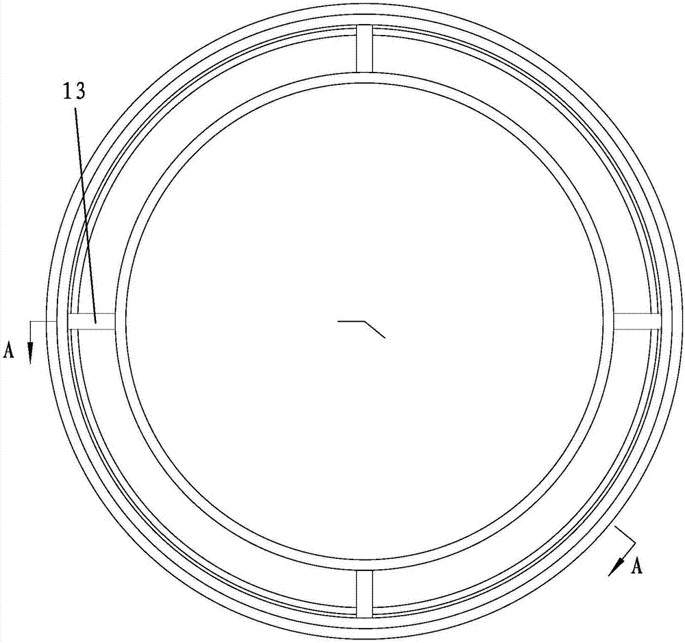
[0034] like Figure 1 to Figure 4 As shown, a fire cover for a burner includes an outer ring fire cover body 1, an annular outer wall body 12, an annular upper wall body 11, and an annular inner wall body 15 of the outer ring fire cover body 1 Surrounded by an annular gas chamber 10 opening downwards, the annular upper wall body 11 and the annular outer side wall body 12 are connected by a number of connecting ribs 13 and there is formed between the two to communicate with the annular gas chamber 10 Several slit-type outward fire hole passages 14, the slit-type outward fire hole passages 14 are arranged obliquely upward from the annular gas chamber 10 to the outer wall of the outer ring fire cover body 1, and the slit-type outward...


PUM


Abstract

The invention discloses a fire cover for a burner. The fire cover comprises an outer ring fire cover body. An annular gas cavity with a downward opening is defined by an annular outer side wall body, an annular upper wall body and an annular inner side wall body of the outer ring fire cover body. The annular upper wall body is connected with the annular outer side wall body through multiple connecting ribs. Multiple slot type outward fire hole channels communicating with the annular gas cavity are formed between the annular upper wall body and the annular outer side wall body. The slot type outward fire hole channels are obliquely and upwardly arranged in the direction from the annular gas cavity to the outer side wall of the outer ring fire cover body, and outward openings of the slot type outward fire hole channels are formed in the outer side wall of the outer ring fire cover body. According to the scheme, the slot type outward fire hole channels are obliquely and upwardly arranged in the direction from the annular gas cavity to the outer side wall of the outer ring fire cover body, and the outward openings of the slot type outward fire hole channels are formed in the outer side wall of the outer ring fire cover body; and more uniform burning and heating of gas are facilitated, the construction is convenient, the channels are not likely to be blocked, and secondary air supplementing is easy.

Description

[0001] [technical field] [0002] The invention relates to a fire cap for use on a burner. [0003] [Background technique] [0004] The fire holes of the existing atmospheric burner generally include: round fire holes, square fire holes, and strip-shaped fire holes. Both the round fire holes and the strip-shaped fire holes are machined. Dozens of fire holes are required on the fire cover, and there are problems such as low production efficiency, a large amount of material waste, and high processing costs; square fire holes are generally made by forging, but due to the large number of fire holes and tolerance requirements, the mold accuracy requirements High, complex mold and short life. [0005] In addition, the above-mentioned fire holes are all independent small holes, and there is still a pain point that it is not easy to clean after being blocked. [0006] A certain burner adopts annular flame holes, which solves the problem of high processing costs of round flame holes, ...

Claims


Application Information

Patent Timeline
IPC IPC(8): F23D14/58
CPCF23D14/586
Inventor 罗峰易洪斌刘嘉龙潘叶江
Owner VATTI CORP LTD
Why Eureka
Try Eureka