
Die-cut parts sticking tooling

A die-cutting and pasting technology, applied in workpiece clamping devices, connecting components, manufacturing tools, etc., can solve the problems of difficult assembly, easy deformation of double-sided tape and foam, and poor pasting accuracy.

Active Publication Date: 2019-02-15
GOERTEK INC
View PDF11 Cites 0 Cited by
  • Summary
  • Abstract
  • Description
  • Claims
  • Application Information

AI Technical Summary

Problems solved by technology

[0003] In industries such as electronics and small parts assembly, there is a common process of sticking die-cut parts. Due to the size restrictions of consumer electronics products, the size of die-cut parts is usually not too large. In some cases, narrow die-cut parts with a width of less than 1mm are even used. Die-cut parts are assembled, and the material of the die-cut parts is soft and easy to deform, making assembly difficult
Many small parts with irregular shapes have irregular incoming materials. Pasting the die-cut parts with automatic equipment requires repositioning the product. The efficiency is low, the cost is high, the action is complicated, and the space is large, so the die-cut parts are often completed by hand. In the actual assembly process, the manual assembly speed is slow, and the double-sided adhesive tape and foam are easy to stick to the side wall, the material scrap rate is high, the efficiency is low, and the accuracy of the pasting is poor, while the double-sided adhesive tape and the foam itself Easy to deform, unable to use automatic assembly

Method used

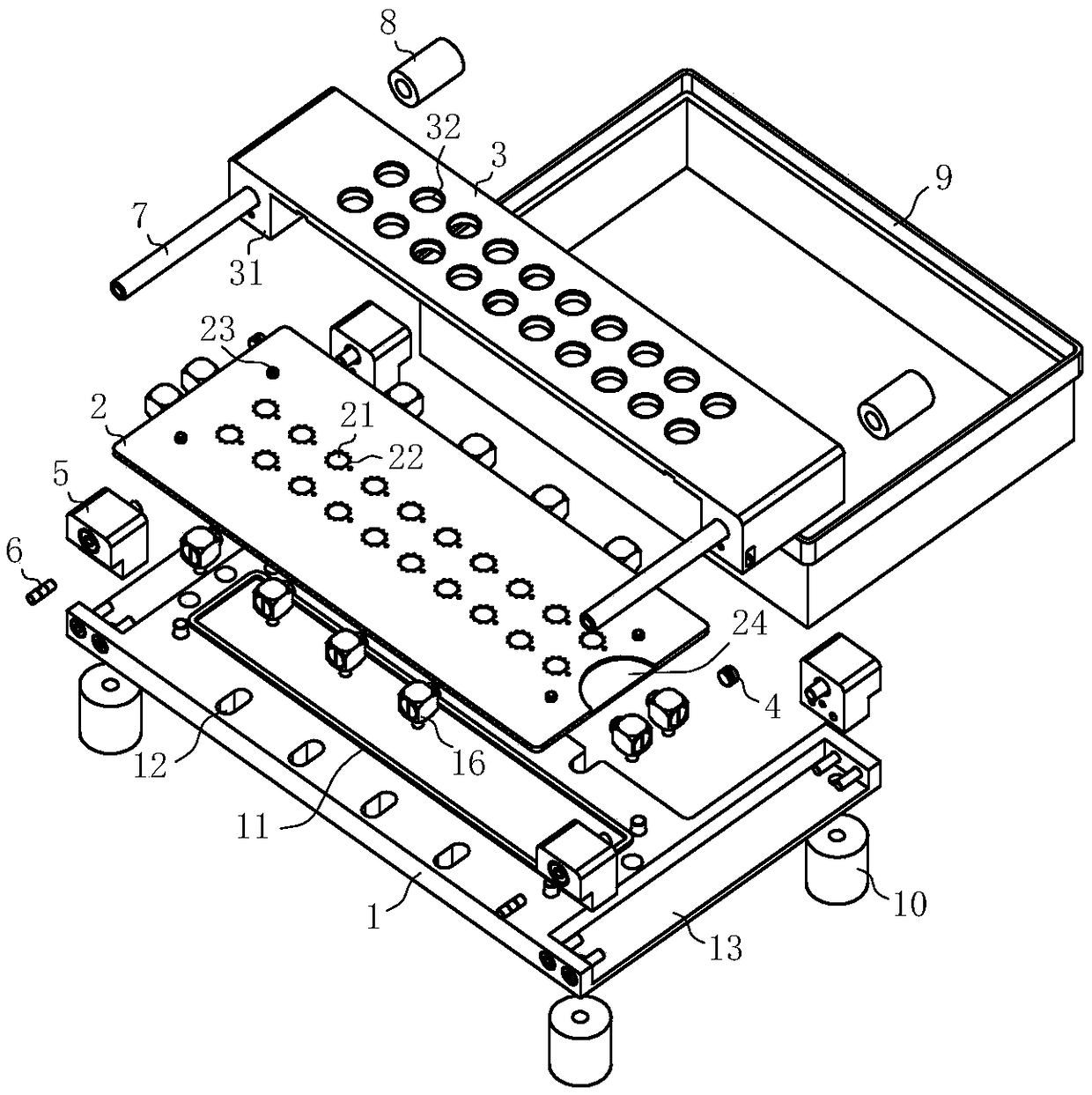
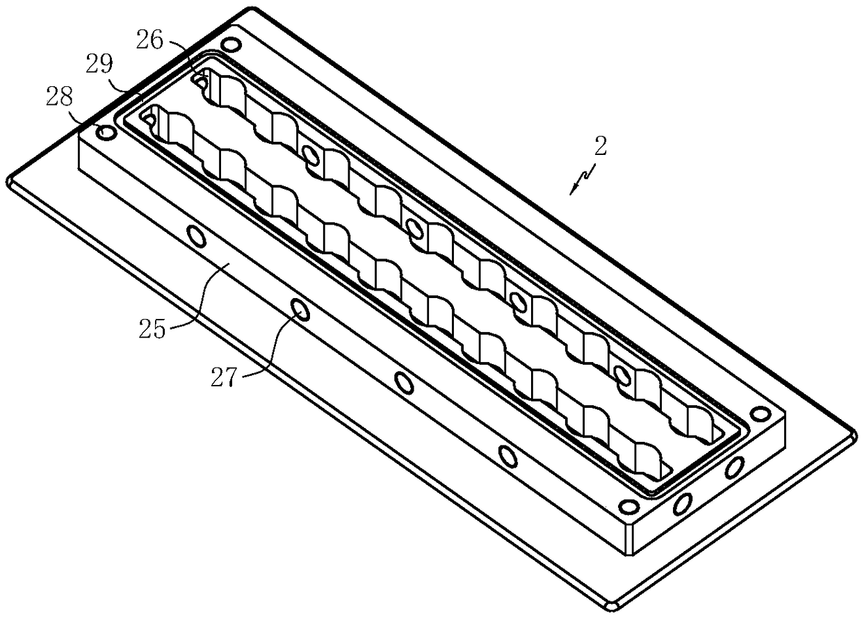
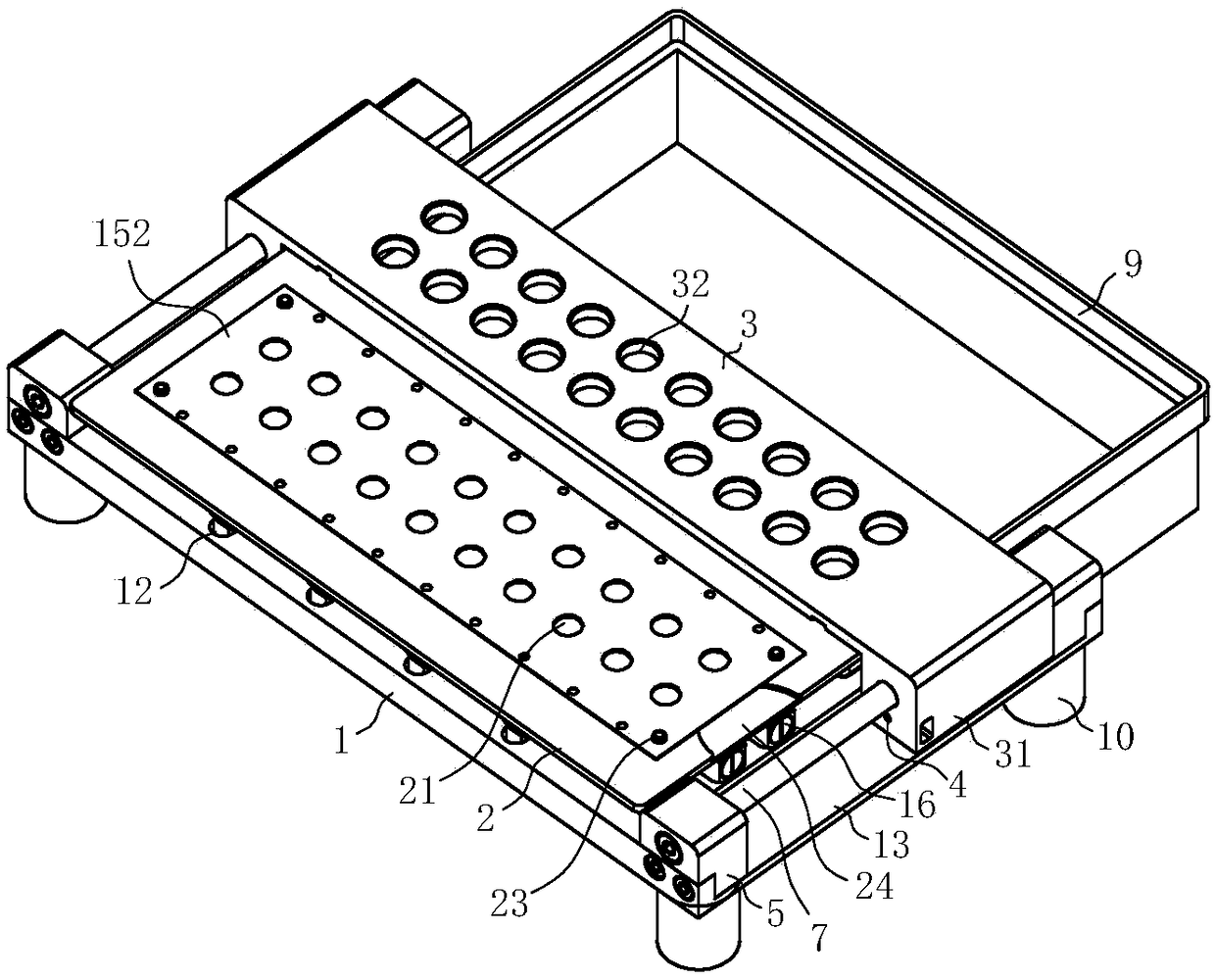

Image

  • Die-cut parts sticking tooling
  • Die-cut parts sticking tooling
  • Die-cut parts sticking tooling

Examples


Embodiment Construction

[0036]In order to make the object, technical solution and advantages of the present invention clearer, the present invention will be further described in detail below in conjunction with the accompanying drawings and embodiments. It should be understood that the specific embodiments described here are only used to explain the present invention, not to limit the present invention.

[0037] The orientations involved in this manual are all based on the orientation of the die-cutting tooling of the present invention when it is working normally, and do not limit its orientation during storage and transportation. It only represents a relative positional relationship, not an absolute positional relationship.

[0038] Such as Figure 1 to Figure 7 As shown, the tooling for sticking die-cut parts includes a base 1, and a fixing plate 2 is provided with a mounting hole 28, and the fixing plate 2 is fixed and installed on the base 1 by bolts; The suction structure includes a product pos...


PUM


Abstract

The invention discloses a die cutting part pasting tool, and relates to the technical field of tools. The die cutting part pasting tool comprises a base and a die cutting part fixing plate fixedly mounted on the base. The fixing plate is provided with multiple locating resorption structures. The locating resorption structures comprise product locating holes and multiple air absorption holes which are located around the product locating holes and correspond to a die cutting part. The air absorption holes communicate with an exhaust device. A profiling block is further included and provided with profiling through holes matched with products. The products correspond to the locating resorption structures after being put into the profiling through holes. According to the die cutting part pasting tool, the die cutting part can be located and guided in the die cutting part pasting process, the assembly difficulty of the die cutting part is reduced, the assembly speed is increased, material scraping losses are reduced, cost is reduced, and work efficiency is improved.

Description

technical field [0001] The invention relates to the technical field of tooling, in particular to a tooling for sticking die-cut pieces. Background technique [0002] Die-cut parts are a type of structural parts widely used in consumer electronics products. Die-cut parts refer to products obtained by rolling and cutting sheets such as double-sided adhesive tape, foam or paper products with a die-cutter according to the shape of the product. In consumer electronics products, die-cut parts are mainly used for bonding , heat insulation, shading, waterproof and dustproof, etc. [0003] In industries such as electronics and small parts assembly, there is a common process of sticking die-cut parts. Due to the size restrictions of consumer electronics products, the size of die-cut parts is usually not too large. In some cases, narrow die-cut parts with a width of less than 1mm are even used. The die-cut parts are assembled, but the material of the die-cut parts is soft and easily ...

Claims


Application Information

Patent Timeline
Patent Type & Authority Patents(China)
IPC IPC(8): F16B11/00B25B11/02
CPCB25B11/02F16B11/006
Inventor 李根钟海鸥
Owner GOERTEK INC
Learn More