Sand core box for bar casting and core making method

A technology for sand cores and castings, which is applied in the field of rod castings, sand core boxes and core making, can solve the problems of not easy to compact the sand layer, difficult operation of cold iron, difficult placement, etc., so as to avoid the placement of cold iron. , The effect of improving the efficiency of core making and simplifying the structure of the core box

Active Publication Date: 2019-04-02
KOCEL EQUIP
View PDF6 Cites 0 Cited by
  • Summary
  • Abstract
  • Description
  • Claims
  • Application Information

AI Technical Summary

Problems solved by technology

[0006] It is very difficult to place chilled iron in the core box, and it is difficult to place. Due to the operation of placing a large number of chilled irons, the sand core needs layered quicksand. For the self-setting resin sand process that is currently the most widely used in the production of large castings, due to The usable time of molding sand is usually no more than 10 minutes. Long-time core making operation is not conducive to the production of high-quality sand cores, and it is easy to cause delamination of sand cores. A large amount of chilled iron will also cause poor surface quality of sand cores, and the final casting surface is uneven. Uneven, and the sand layer between a large number of cold irons is not easy to compact, which can easily cause quality problems such as sand inclusions in castings

Method used


Image

  • Sand core box for bar casting and core making method
  • Sand core box for bar casting and core making method
  • Sand core box for bar casting and core making method

Examples


Embodiment Construction

[0028] In order to more clearly illustrate the technical solutions of the embodiments of the present invention, the following will briefly introduce the accompanying drawings that need to be used in the embodiments. Obviously, the accompanying drawings in the following description are some embodiments of the present invention. Ordinary technicians can also obtain other drawings based on these drawings on the premise of not paying creative work.

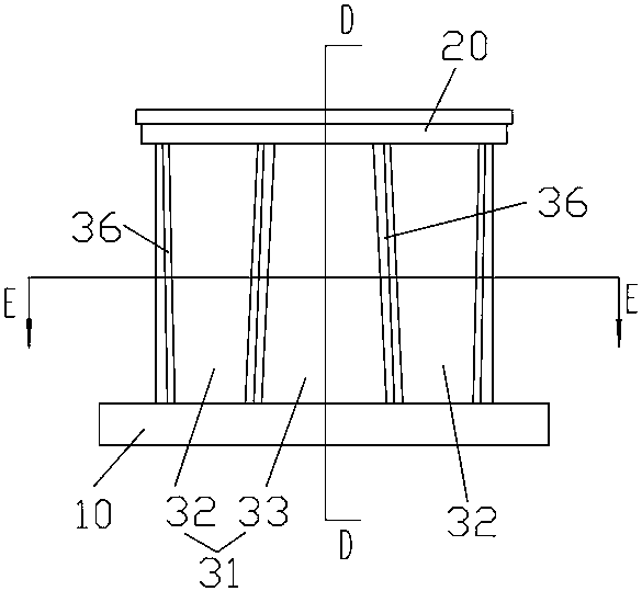
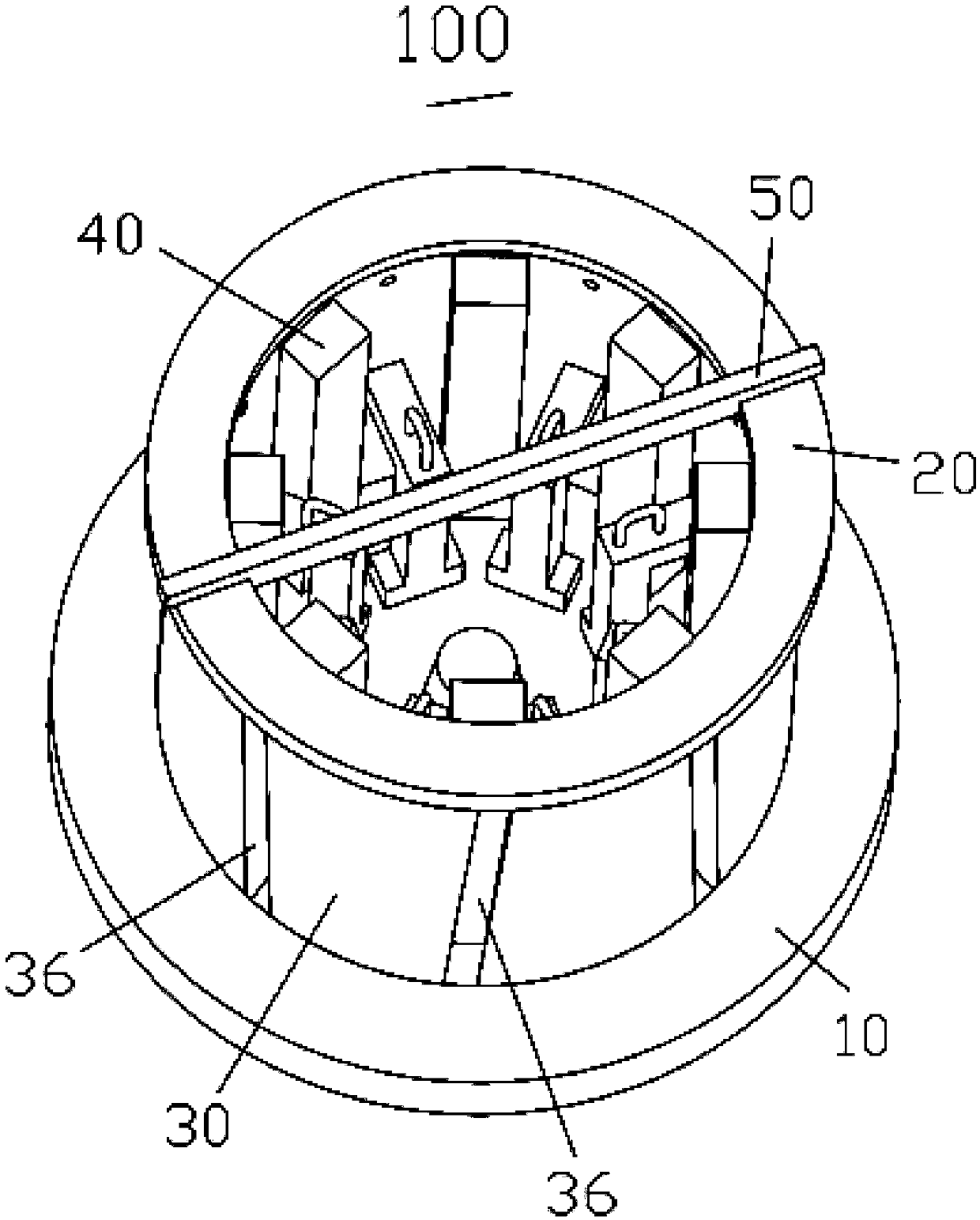
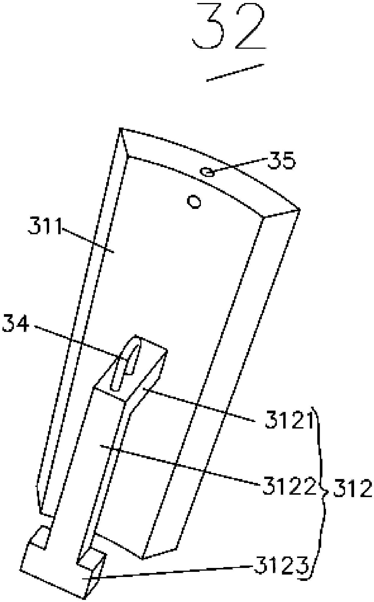
[0029] see Figure 1 to Figure 10 , the embodiment of the present invention provides a sand core box 100 for rod castings, including a positioning bottom plate 10, a positioning top plate 20, and a spliced ​​positioning side wall 30. The upper surface of the positioning bottom plate 10 is provided with a lower positioning groove 14, and the positioning top plate 20 The lower surface is provided with an upper positioning groove 21, the spliced ​​positioning side wall 30 is a hollow cylinder, the top of the spliced ​​positioning side wa...


PUM


Abstract

A stick type casting sand core box comprises a positioning bottom plate, a positioning top plate and a spliced type positioning side wall. The upper surface of the positioning bottom plate is provided with a lower positioning groove, the lower surface of the positioning top plate is provided with an upper positioning groove, and the spliced type positioning side wall is a hollow cylinder. The top of the spliced type positioning side wall is embedded into the upper positioning groove of the positioning top plate, and the bottom of the spliced type positioning side wall is embedded into the lower positioning groove of the positioning bottom plate. The spliced type positioning side wall comprises a plurality of pieces of core iron, the core iron is provided with an arc-shaped body, the core iron is arrayed in the circumferential direction to form the spliced type positioning side wall, and the adjacent core iron does not make contact so that receding gaps can be formed. According to the core box, by manufacturing the blocky and independent core iron, the core box structure is simplified, placement of a large number of chilling blocks in the core manufacturing process is avoided, and the core manufacturing efficiency is improved. The core iron has the effect of the chilling blocks and forms the side wall of the core box, and a double beneficial effect is achieved.

Description

technical field [0001] The invention relates to the technical field of core boxes for sand casting, in particular to a sand core box for rod castings and a core-making method. Background technique [0002] The sand core used for the cavity forming of large rod castings is a cylinder, such as Figure 11 . [0003] The ball mill trunnion used for a large ball mill is a large rod casting. The feed end and discharge end of a large ball mill are usually composed of a basin-shaped end cover and a connected cylindrical trunnion. The material is usually nodular Cast iron or cast steel, the production of trunnions using the sand casting process is a common method. However, due to the large wall thickness of the trunnion, the cooling capacity of the sand mold cavity is insufficient, and the shrinkage tendency of the ductile iron or cast steel trunnion produced by the sand casting method is very large. In the process of producing ball mill trunnion by sand casting, in order to ensure...

Claims


Application Information

Patent Timeline
Patent Type & Authority Patents(China)
IPC IPC(8): B22C7/06B22C9/10
CPCB22C7/06B22C9/10
Inventor 张守全戚梦林宋亮于苏杭
Owner KOCEL EQUIP
Why Eureka
Try Eureka