Eureka AIR delivers breakthrough ideas for toughest innovation challenges, trusted by R&D personnel around the world.

Automatic round pipe punching machine capable of being applied to production line

A punching machine and production line technology, applied in the field of stamping equipment, can solve the problems of not being able to automatically take materials and cannot meet the continuous operation of the production line, and achieve the effects of reducing human intervention, wide application range, and simple material taking process

Active Publication Date: 2017-07-28
HEBEI UNIV OF TECH
View PDF8 Cites 2 Cited by
  • Summary
  • Abstract
  • Description
  • Claims
  • Application Information

AI Technical Summary

Problems solved by technology

It is necessary to send the round pipe from the feeding chute into the punching machine outside the punching machine, which cannot meet the continuous operation of the production line and cannot automatically pick up the material

Method used


Image

  • Automatic round pipe punching machine capable of being applied to production line
  • Automatic round pipe punching machine capable of being applied to production line
  • Automatic round pipe punching machine capable of being applied to production line

Examples


Embodiment Construction

[0026] In order to make the objectives, technical solutions, and advantages of the present invention clearer, the following further describes the invention in detail in conjunction with specific embodiments and with reference to the accompanying drawings. It should be understood that these descriptions are only exemplary, and are not intended to limit the protection scope of the claims of the present invention. In addition, in the following description, descriptions of well-known structures and technologies are omitted to avoid unnecessarily obscuring the concept of the present invention.

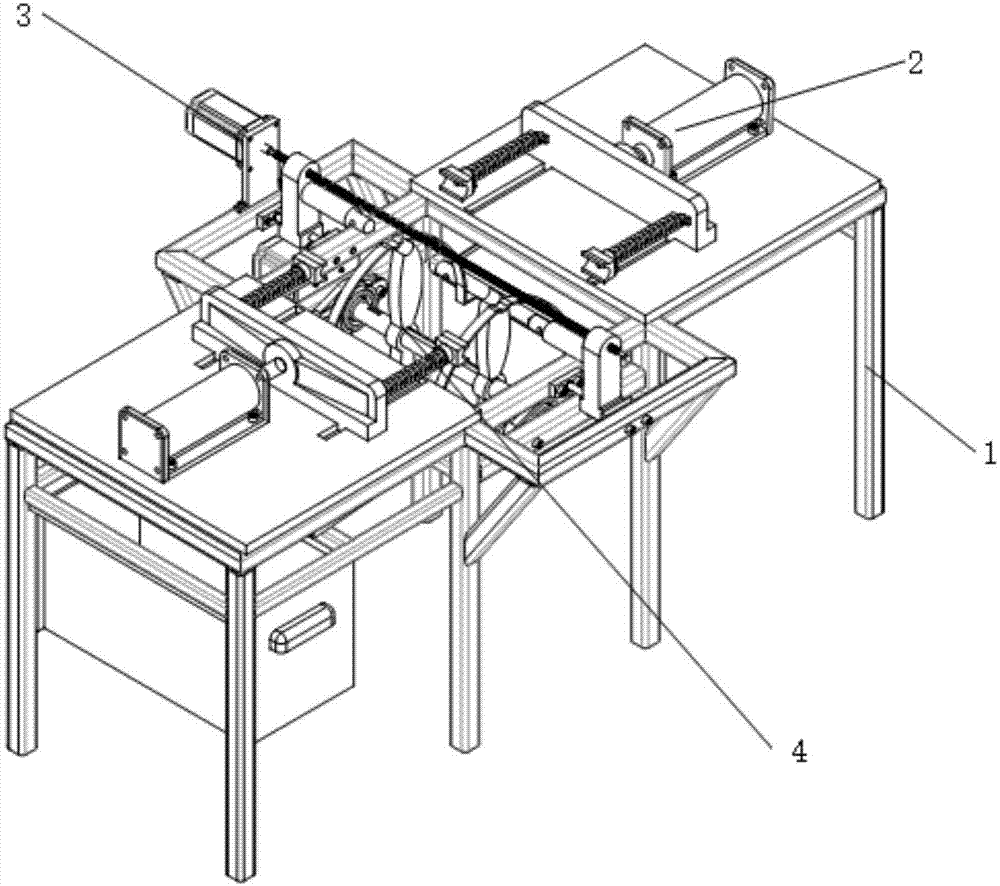
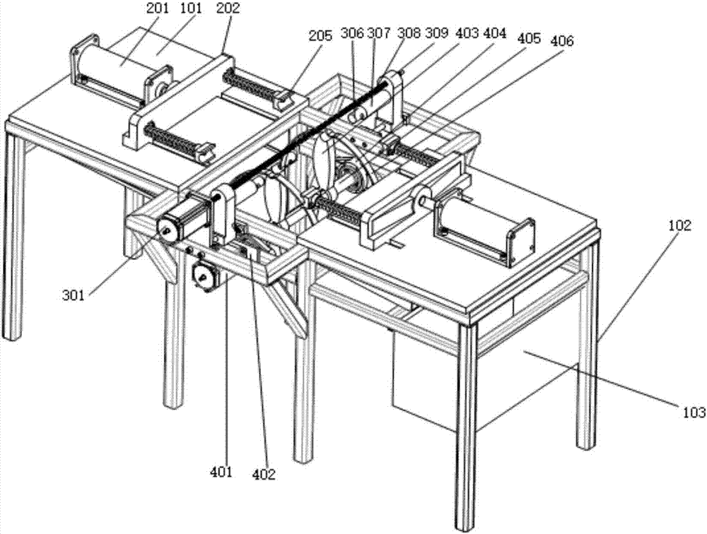
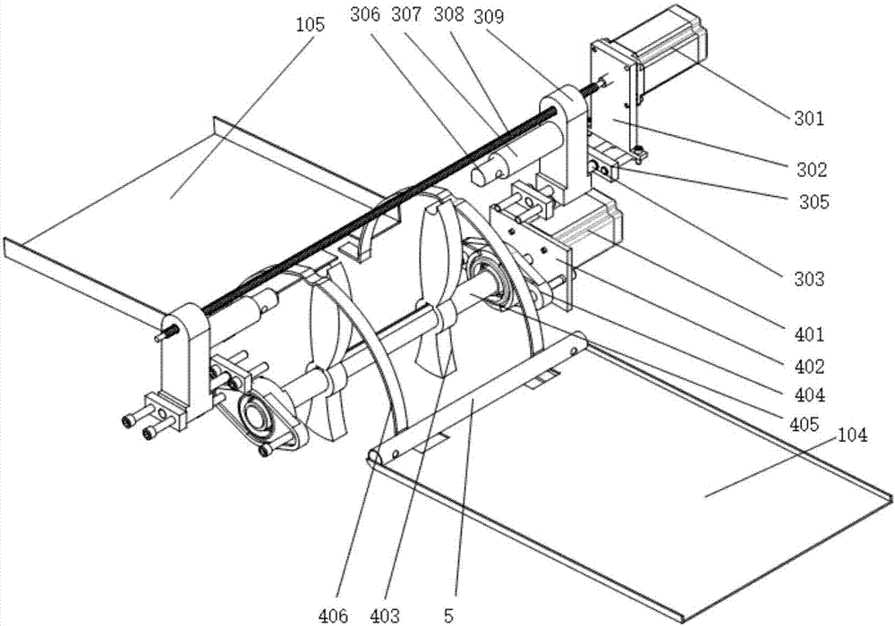
[0027] The invention can be used in the automatic round pipe punching machine of the production line, (see Figure 1-2 ) Including platform 1, punching device 2, positioning device 3 and reclaiming device 4;

[0028] The platform 1 includes a support 102, two support plates 101, a hopper 103, a feed steel pipe storage support 104, and a discharge steel pipe storage support 105. The support 102 ...


PUM


Abstract

The invention relates to an automatic round pipe punching machine capable of being applied to a production line. The automatic round pipe punching machine capable of being applied to the production line comprises a platform, a punching device, a locating device and a material fetching device. The round pipe punching machine capable of being applied to the production line is characterized in that the platform comprises a support, two supporting plates, a hopper, a feeding steel tube storage support and a discharging steel tube storage support, the support comprises a middle portion, a left portion and a right portion, the left portion and the right portion are symmetrical about the middle portion, the two supporting plates are fixed to the upper surface of the left portion and the right portion correspondingly, the two steel tube storage supports are fixed to the portions, below the two supporting plates, of the support, the left side of each steel tube storage support is lower than the right side of the steel tube storage support, a plurality of gaps are formed in the corresponding positions of the inner sides of each steel tube storage support, the steel tube storage support located on the right side is the feeding steel tube storage support, the steel tube storage support on the left side is the discharging steel tube storage support, the included angle between the feeding steel tube storage support and the horizontal plane is beta, the included angle between the discharging steel tube storage support and the horizontal plane is alpha, and the angle beta and the angle alpha can guarantee that steel tubes can roll off from left to right through the gravity on the feeding steel tube storage support and the discharging steel tube storage support.

Description

Technical field [0001] The invention relates to the technical field of stamping equipment, in particular to an automatic round pipe punching machine that can be used in a production line. Background technique [0002] With the progress of society, the increase of labor costs, and the improvement of production automation, a device that can be used in the production line to continuously punch steel pipes is required, and human intervention is reduced. The Chinese patent with application number 2015110144297 discloses a fully automatic round pipe punching machine, which includes a working table, a cylinder bracket is arranged on the working table, a cylinder is arranged above the cylinder bracket, and the output end of the cylinder is vertical It passes straight down through the cylinder support, the output end of the cylinder is fixedly connected with a punch, and a die seat is provided under the punch. It is necessary to manually place the round pipe in the groove of the workbenc...

Claims


Application Information

Patent Timeline
IPC IPC(8): B21D28/28B21D28/34B21D43/00B21D43/04B21D43/20B21D45/02
CPCB21D28/28B21D28/34B21D43/003B21D43/006B21D43/04B21D43/20B21D45/02
Inventor 戚开诚杨飞飞张建军吴锦辉李启腾
Owner HEBEI UNIV OF TECH
Why Eureka
Eureka Blog
Learn More