
Method for detecting thickness and surface topography of respective layer inside lithium ion battery

A lithium-ion battery and surface topography technology, applied in measuring devices, instruments, using ultrasonic/sonic/infrasonic waves, etc., can solve the problems of low resolution, damage to samples, fast attenuation, etc., to achieve simple operation and low equipment investment , Easy to operate effect

Active Publication Date: 2017-07-25
CHINA ELECTRIC POWER RES INST +2
View PDF19 Cites 8 Cited by
  • Summary
  • Abstract
  • Description
  • Claims
  • Application Information

AI Technical Summary

Problems solved by technology

[0005] Low-frequency ultrasonic waves have strong penetration but low resolution. High-frequency ultrasonic waves show better resolution but attenuate quickly when passing through samples of the same thickness. Adjusting the ultrasonic pulse energy can provide greater penetrating power but it is possible Generates heat and damages the sample, so choosing the right ultrasonic frequency for the test is critical

Method used


Image

  • Method for detecting thickness and surface topography of respective layer inside lithium ion battery
  • Method for detecting thickness and surface topography of respective layer inside lithium ion battery
  • Method for detecting thickness and surface topography of respective layer inside lithium ion battery

Examples


Embodiment 1

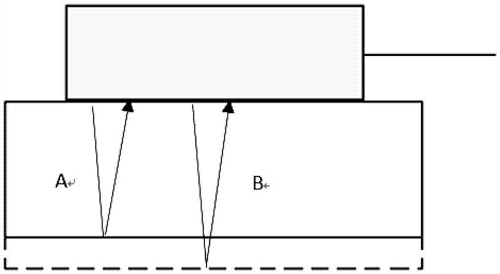
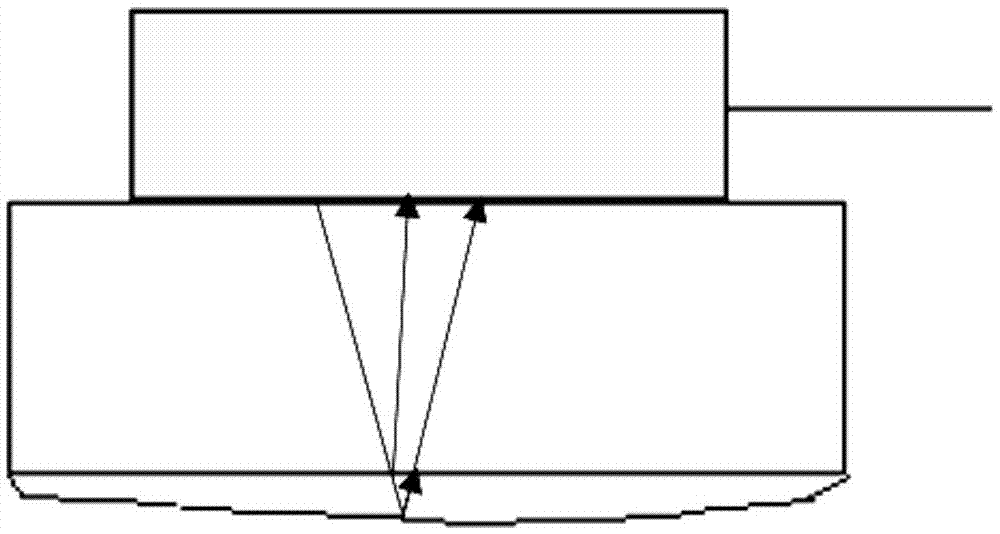
[0046] Use the steel sheet as the substrate, use the ultrasonic probe with a frequency of 10MHz as the ultrasonic pulse transmitter, take a certain amount of coupling agent and apply it on the contact surface between the steel sheet and the ultrasonic generating / receiving probe, make close contact, turn on the oscilloscope and pulse generator, and adjust the ultrasonic frequency The test is carried out until it matches the thickness of the sample, and the test result is analyzed to obtain the periodic signal of the thickness of the steel sheet. Such as figure 2 shown.

Embodiment 2

[0048]Use aluminum foil as the substrate, use the ultrasonic probe with a frequency of 10MHz as the ultrasonic pulse transmitter, take a certain amount of couplant and apply it on the contact surface between the aluminum foil and the ultrasonic generating / receiving probe, and make close contact, turn on the oscilloscope and pulse generator, and adjust the ultrasonic frequency to match The thickness of the sample is consistent, the test is carried out, and the test result is analyzed to obtain the periodic signal of the thickness of the aluminum foil.

Embodiment 3

[0050] Use the positive shell as the substrate, and use the ultrasonic probe with a frequency of 10MHz as the ultrasonic pulse transmitter. Take a certain amount of couplant and apply it on the contact surface between the positive shell and the ultrasonic generating / receiving probe, make close contact, turn on the oscilloscope and pulse generator, and adjust the ultrasonic frequency. The test is carried out until it matches the thickness of the sample, and the test result is analyzed to obtain a periodic signal of the thickness of the positive electrode shell.


PUM


Abstract

The invention relates to a method for detecting thickness and surface topography of respective layer inside a lithium ion battery. The method includes the following steps: 1. selecting a to-be-tested sample; 2. acquiring a waveform signal prior to the test of the to-be-tested sample; 3. assembling the tested sample in battery test; 4. collecting the assembled sample and acquiring the waveform signal of the assembled sample after the test; 5. comparing the waveform signal after the test with an initial waveform signal of the tested sample, and analyzing the difference of the two in terms of thickness and topography; and 6. determining changes of the sample in terms of thickness and surface topography. According to the invention, the technical solution, by measuring the thickness and surface topography of each layer inside the lithium ion battery, obtains the changes of the lithium ion battery during usage in terms of thickness and surface topography, locates safety hazards inside the lithium ion battery, and increases the safety of the lithium ion battery during usage.

Description

technical field [0001] The invention relates to the technical field of energy storage, and more specifically relates to a detection method for the thickness and surface topography of each layer inside a lithium-ion battery. Background technique [0002] During the use of lithium-ion batteries, the thickness and surface morphology of the internal layers (battery shell, positive electrode, negative electrode and separator) will change, some of these changes are reversible, and some are irreversible. Among these irreversible changes, as the degree of change increases, defects may be formed inside the battery, increasing hidden dangers during battery use. The current analysis method for the thickness and surface morphology of each layer inside the lithium-ion battery is mainly to disassemble the battery in a glove box with extremely low moisture and oxygen content, measure the thickness of each layer, and then process the samples of each layer , conduct scanning electron micros...

Claims


Application Information

Patent Timeline
Patent Type & Authority Applications(China)
IPC IPC(8): G01B17/00
CPCG01B17/00
Inventor 金翼张遥骋范茂松林跃生王绥军傅凯刘曙光闫雪生褚永金
Owner CHINA ELECTRIC POWER RES INST
Learn More