
Embedding jig of module power supply and embedding device with embedding jig

A module power supply and fixture technology, which is applied in the field of potting and sealing technology, can solve the problems that the glue cannot flow, the bubbles of the module power supply cannot be eliminated, and the life of the module power supply is shortened, so as to achieve the effect of quality assurance

Inactive Publication Date: 2017-07-21
SHENZHEN XETAR TECH
View PDF5 Cites 3 Cited by
  • Summary
  • Abstract
  • Description
  • Claims
  • Application Information

AI Technical Summary

Problems solved by technology

With the extensive use of semiconductor technology, packaging technology and high-frequency soft switching, the power density of the module power supply is getting higher and higher, and the conversion efficiency is getting higher and higher; however, in order to realize high-power and high-density modules, the volume of the module power supply Small, and the electronic components are becoming more and more dense. At present, in order to achieve heat dissipation, pressure resistance, shockproof, waterproof and moisture-proof, high and low temperature environments, insulation, and its physical and electrical properties, it can only be potted and sealed, making it complicated. The structure and shape can be effectively protected for a long time
At present, in the process of potting the module power supply on the market, the rubber material cannot flow in the ideal direction, resulting in the encapsulation of the module power supply (especially the small gap and the position of the water chestnut) cannot be eliminated, resulting in the module during the potting process and after curing. There are air bubbles in the power supply, which will shorten the life of the module power supply or scrap it during use

Method used


Image

  • Embedding jig of module power supply and embedding device with embedding jig
  • Embedding jig of module power supply and embedding device with embedding jig
  • Embedding jig of module power supply and embedding device with embedding jig

Examples


Embodiment Construction

[0022] The present invention will be further described below with reference to the accompanying drawings and in combination with preferred embodiments.

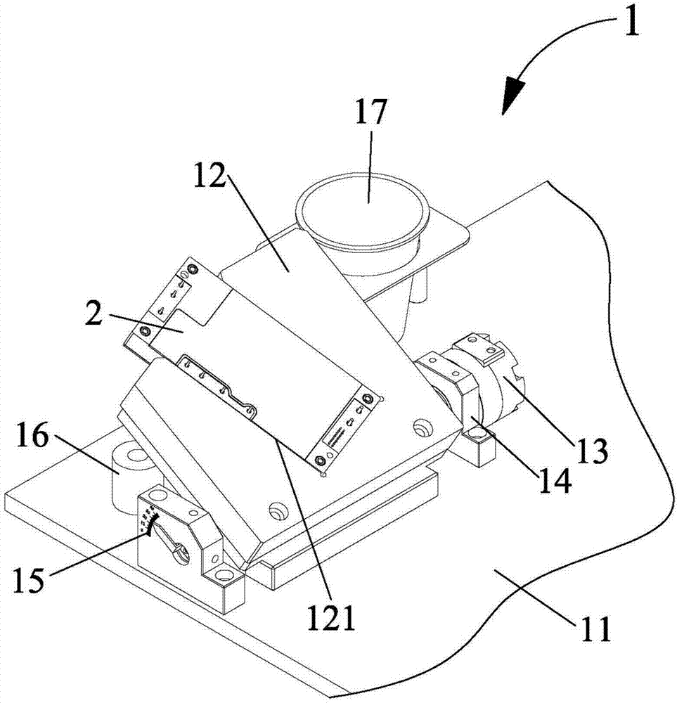
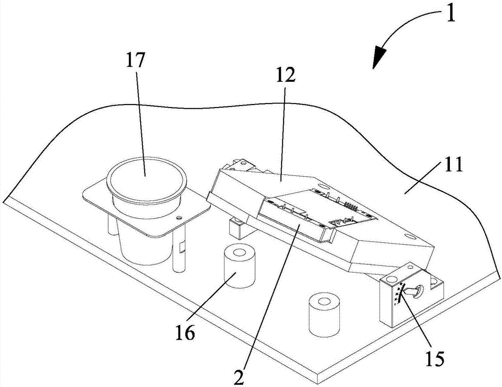
[0023] like figure 1 and figure 2 As shown, it is a schematic structural diagram of the potting fixture 1 of the preferred embodiment of the present invention. The potting fixture 1 includes a fixture base 11, a fixture main body 12, a cylinder 13, a base 14, an angle indicator 15, and a cushion 16 and a waste cup 17, wherein the jig main body 12 is used to fix the module power supply 2 to be potted, and the jig main body 12 is rotatably connected to the jig base 11 to drive the power supply 2 of the to-be-potted module to rotate; the jig main body 12 is provided with a concave Groove 121, the groove 121 is matched with the power supply 2 of the module to be potted, so that the power supply 2 of the module to be potted can be quickly positioned and fixed on the jig body 12, and ensure that no deviation occurs during the rot...


PUM


Abstract

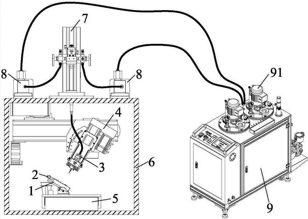
The invention discloses an embedding jig of a module power supply and an embedding device with the embedding jig. The embedding jig comprises a jig base and a jig main body, wherein the jig main body is rotatably connected on the jig base; and the jig main body is used for fixing the to-be-embedded module power supply. The embedding device comprises a feeding mechanism, a glue filling mechanism and the embedding jig, wherein the feeding mechanism is used for providing glue for the glue filling mechanism; the glue filling mechanism is used for performing embedding on the to-be-embedded module power supply; and the embedding jig is arranged below the glue filling mechanism. According to the embedding jig of the module power supply and the embedding device with the embedding jig provided by the invention, air in bubbles can be smoothly discharged during the embedding process, a cavity of the to-be-embedded module power supply can be completely filled with glue, and quality of the module power supply is guaranteed.

Description

technical field [0001] The invention relates to the field of potting technology, in particular to a potting jig for a module power supply and potting equipment with the potting jig. Background technique [0002] Due to the characteristics of short design cycle, high reliability and easy system upgrade, the modular power supply system is widely used in switching equipment, mobile communication, microwave communication, access equipment, optical transmission, routers and other communication fields and automotive electronics, In aerospace and other fields, especially in recent years, due to the rapid development of data services and the continuous promotion of distributed power supply systems, the application of module power supplies has become more and more extensive. With the extensive use of semiconductor technology, packaging technology and high-frequency soft switching, the power density of the module power supply is getting higher and higher, and the conversion efficiency...

Claims


Application Information

Patent Timeline
IPC IPC(8): B29C70/72
CPCB29C70/72
Inventor 刘自华袁尊钢
Owner SHENZHEN XETAR TECH
Learn More