
A bag filter

A technology of bag filter and dust removal chamber, which is applied in the direction of chemical instruments and methods, separation methods, and separation of dispersed particles, which can solve the problems of increased filter bag load, increased pressure difference in dust removal chamber, and uneven air distribution, achieving secondary The probability of dust raising is reduced, the uneven distribution of the flow field is reduced, and the filtration efficiency is high.

Active Publication Date: 2022-07-01
JIANGSU UNIV OF SCI & TECH
View PDF20 Cites 0 Cited by
  • Summary
  • Abstract
  • Description
  • Claims
  • Application Information

AI Technical Summary

Problems solved by technology

[0002] The bag filter plays an important role in the field of environmental protection, and the deflector is one of the important parts of the dust collector, which is used to guide the flue gas flow and optimize the distribution of the air flow. If it is in direct contact with the filter bag, the washing of the high-speed flue gas will increase the load of the filter bag, aggravate the wear of the filter bag and reduce the dust removal efficiency, which will cause extensive damage to the filter bag, uneven airflow and pressure distribution, and greatly reduce the dust removal efficiency of the dust collector. reduce
[0003] Patent No. CN201410284325.7 proposes a trough deflector. The deflector has poor structural strength and uneven distribution of smoke from the deflector. If the smoke is too concentrated, it is easy to cause bag breakage and flow through the deflector. The smoke flow rate at the bottom of the plate is too fast, etc.
Due to the internal pressure and the relatively large aspect ratio of the deflector when the dust collector is running, the deflector is prone to large deformation under the internal pressure of the dust collector, and the pressure on each plate is uneven, resulting in inconsistent deformation. An additional support structure is needed to ensure that its strength meets the requirements, and the additional support structure will damage the uniformity of the air flow field at the inlet, which will lead to uneven air distribution and turbulence of the air flow by the deflector, and the air guide effect As a result, the pressure difference in the dust removal chamber is increased, the deformation is further aggravated, the air distribution is more uneven, and a vicious circle is formed, which finally makes the effect of the deflector greatly reduced, and the additional reinforced support parts will cause the cost to increase and the economy to decline; Due to the defect of the deflector structure, part of the flue gas entering the pre-dust removal chamber rises upwards after contacting the deflector, and forms a large eddy current after contacting the flower plate, which affects the uniformity of the air flow field and also makes the passing through The velocity of the flue gas passing through the deflector and in contact with the side of the filter bag is accelerated, and the flue gas vertically downward along the notch is at the end of the deflector because there is no flow diversion measure and the flow space is instantly reduced, resulting in The flow velocity of the flue gas here will instantly increase, and the maximum velocity of the entire flow field is also formed here, so that the flue gas enters the dust removal chamber at a high speed, and it is easy to roll up the flue dust in the ash hopper to form secondary dust, thereby It affects the uniformity of the flow field and the service life of the filter bag, which in turn causes the dust removal efficiency of the dust collector to decrease

Method used


Image

  • A bag filter
  • A bag filter
  • A bag filter

Examples


Embodiment 1

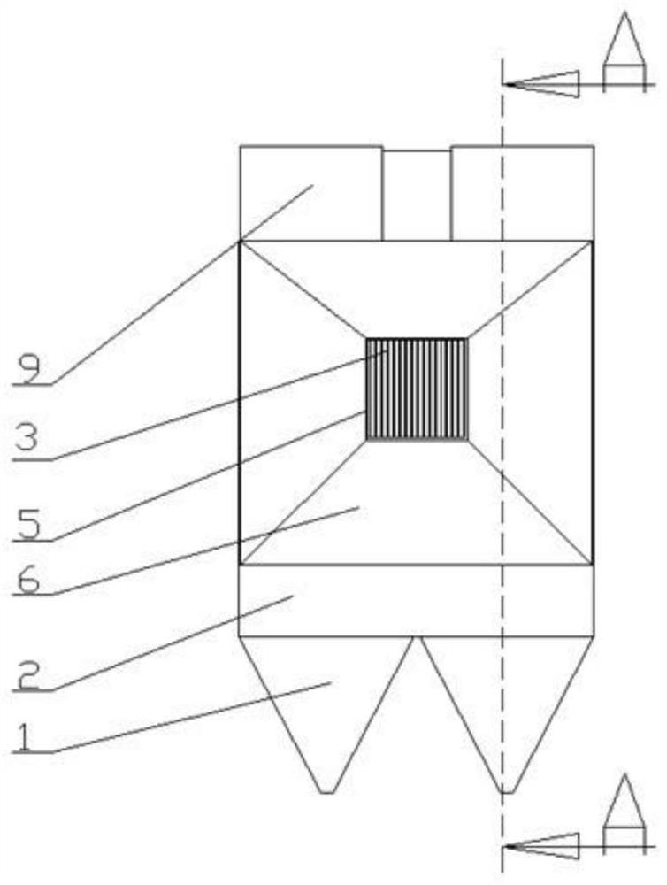
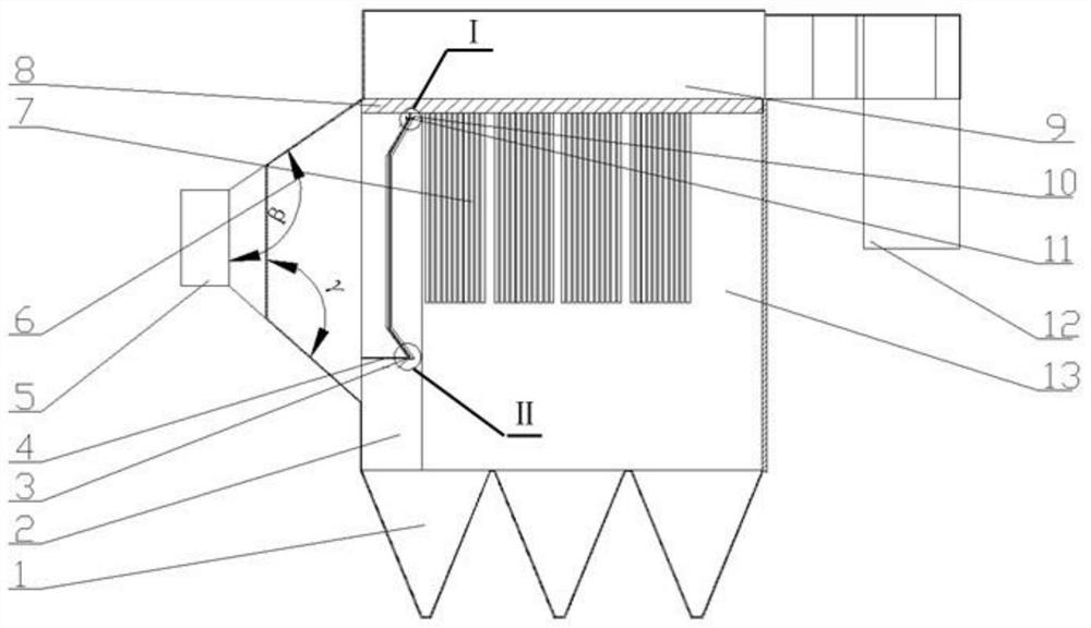
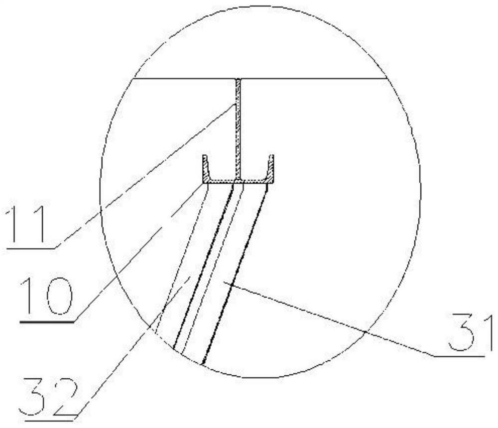
[0027] like figure 1 , figure 2 , image 3 and Figure 4 Shown: a bag-type dust collector, including a box body, the interior of the box body is horizontally arranged with a flower plate 8, and the flower plate 8 divides the box body into an upper clean air chamber 9 and a lower box body 2, so The middle of the lower box body 2 is vertically arranged with a partition plate 13, the partition plate 13 divides the lower box body 2 into two left and right dust chambers, and the lower part of the lower box body 2 is installed with a number of dust collectors that communicate with it. Bucket 1, the side of the lower box body 2 is provided with an air inlet bell mouth 6, the air inlet bell mouth 6 includes an upper bell mouth and a lower bell mouth, and the opening angle of the upper bell mouth is the upper opening angle β, so The opening angle of the lower bell mouth is the lower opening angle γ, the end of the air inlet bell mouth 6 is provided with a straight air inlet 5, the ...

Embodiment 2

[0033] refer to figure 1 , figure 2 , image 3 and Figure 4 Shown: a bag-type dust collector, including a box body, the interior of the box body is horizontally arranged with a flower plate 8, and the flower plate 8 divides the box body into an upper clean air chamber 9 and a lower box body 2, so The middle of the lower box body 2 is vertically arranged with a partition plate 13, the partition plate 13 divides the lower box body 2 into two left and right dust chambers, and the lower part of the lower box body 2 is installed with a number of dust collectors that communicate with it. Bucket 1, the side of the lower box body 2 is provided with an air inlet bell mouth 6, the air inlet bell mouth 6 includes an upper bell mouth and a lower bell mouth, and the opening angle of the upper bell mouth is the upper opening angle β, so The opening angle of the lower bell mouth is the lower opening angle γ, the end of the air inlet bell mouth 6 is provided with a straight air inlet 5, ...

Embodiment 3

[0039] refer to figure 1 , figure 2 , image 3 and Figure 4 Shown: a bag-type dust collector, including a box body, the interior of the box body is horizontally arranged with a flower plate 8, and the flower plate 8 divides the box body into an upper clean air chamber 9 and a lower box body 2, so The middle of the lower box body 2 is vertically arranged with a partition plate 13, the partition plate 13 divides the lower box body 2 into two left and right dust chambers, and the lower part of the lower box body 2 is installed with a number of dust collectors that communicate with it. Bucket 1, the side of the lower box body 2 is provided with an air inlet bell mouth 6, the air inlet bell mouth 6 includes an upper bell mouth and a lower bell mouth, and the opening angle of the upper bell mouth is the upper opening angle β, so The opening angle of the lower bell mouth is the lower opening angle γ, the end of the air inlet bell mouth 6 is provided with a straight air inlet 5, ...


PUM

PropertyMeasurementUnit
radiusaaaaaaaaaa

Abstract

The invention provides a bag-type dust collector, which includes a box body, a pattern plate is arranged in the box body, and the box body is divided into an upper clean air chamber and a lower box body, the lower box body is provided with a plurality of ash hoppers, and the lower box body is provided with an air inlet The bell mouth, the flower plate is provided with several filter bags, the air inlet bell mouth and the lower box are provided with a deflector, the deflector includes a front deflector and a rear deflector, and the front deflector has a cross section of It is composed of semicircular guide grooves, the rear guide plate is composed of semicircular guide grooves with straight plates tangent to it on both sides, and the guide grooves of the front guide plate and the rear guide plate are divided into two parts. The openings are all facing the direction of the air inlet bell mouth, and both ends of the deflector are bent along the direction of the flue gas and have transition arcs. By changing the structure and installation arrangement of the deflector, the flue gas can enter Before the dust chamber, the large particles are subjected to inertial sedimentation, and it has stronger rigidity and greatly reduces the amount of deformation. It can also better realize the secondary distribution of the flue gas, and avoid the phenomenon of bag breaking due to excessive concentration of the flue gas. .

Description

technical field [0001] The invention relates to a bag-type dust collector, in particular to a bag-type dust collector with an air intake guide plate with a special structure, and belongs to the technical field of dust collectors. Background technique [0002] The bag filter plays an important role in the field of environmental protection, and the deflector is one of the important components of the dust collector, which is used to guide and optimize the airflow of the smoke and dust. Due to the large inlet speed of the smoke and dust particles entrained, If it is in direct contact with the filter bag, the scouring of high-speed flue gas will increase the load of the filter bag, aggravate the wear of the filter bag and reduce the dust removal efficiency, which will lead to extensive damage to the filter bag, uneven distribution of air flow and pressure, resulting in a large dust removal efficiency of the dust collector. reduce. [0003] The document with the patent number of ...

Claims


Application Information

Patent Timeline
Patent Type & Authority Patents(China)
IPC IPC(8): B01D50/20
CPCB01D50/20
Inventor 张礼华孙国龙顾振鹏
Owner JIANGSU UNIV OF SCI & TECH
Learn More