Rotating handle table tennis bat
A table tennis racket, rotating handle technology, applied in the direction of racket, sports accessories, etc., can solve the problem that the handle cannot be rotated, and achieve the effect of enhancing adaptability and facilitating the angle of the handle
- Summary
- Abstract
- Description
- Claims
- Application Information
AI Technical Summary
Problems solved by technology
Method used
Image
Examples
Embodiment 1
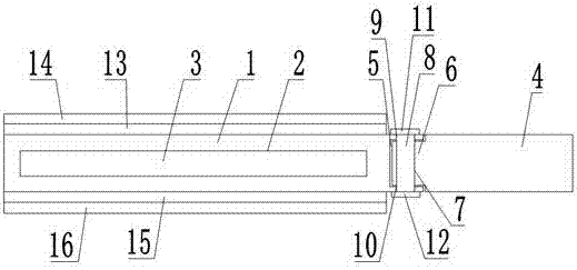
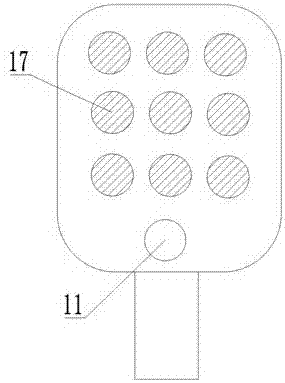
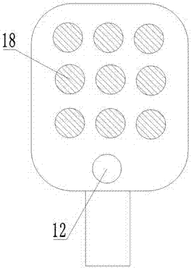
[0022] A table tennis racket with a rotating handle, comprising a base plate 1 and a handle 4, the base plate 1 is provided with a cavity 2, the cavity 2 is filled with a sponge interlayer 3, the bottom end of the base plate 1 is provided with a long groove 5, and the long groove 5 is provided with a connection Column 8, the top of the handle 4 is provided with a connecting portion 6, the connecting portion 6 is provided with a hinge hole 7, the connecting column 8 is located in the hinged hole 7, the connecting portion 6 is located in the long groove 5, and the side of the long groove 5 is provided with a first pass Groove 9, the other side is provided with the second through groove 10, and one end of connecting column 8 is positioned in the first through groove 9, and the other end is positioned in the second through groove 10, and one end of connecting column 8 is provided with the first limiting plate 11, and another One end is provided with a second limiting plate 12, the ...
Embodiment 2
[0026] A table tennis racket with a rotating handle, comprising a base plate 1 and a handle 4, the base plate 1 is provided with a cavity 2, the cavity 2 is filled with a sponge interlayer 3, the bottom end of the base plate 1 is provided with a long groove 5, and the long groove 5 is provided with a connection Column 8, the top of the handle 4 is provided with a connecting portion 6, the connecting portion 6 is provided with a hinge hole 7, the connecting column 8 is located in the hinged hole 7, the connecting portion 6 is located in the long groove 5, and the side of the long groove 5 is provided with a first pass Groove 9, the other side is provided with the second through groove 10, and one end of connecting column 8 is positioned in the first through groove 9, and the other end is positioned in the second through groove 10, and one end of connecting column 8 is provided with the first limiting plate 11, and another One end is provided with a second limiting plate 12, the ...
Embodiment 3
[0030] A table tennis racket with a rotating handle, comprising a base plate 1 and a handle 4, the base plate 1 is provided with a cavity 2, the cavity 2 is filled with a sponge interlayer 3, the bottom end of the base plate 1 is provided with a long groove 5, and the long groove 5 is provided with a connection Column 8, the top of the handle 4 is provided with a connecting portion 6, the connecting portion 6 is provided with a hinge hole 7, the connecting column 8 is located in the hinged hole 7, the connecting portion 6 is located in the long groove 5, and the side of the long groove 5 is provided with a first pass Groove 9, the other side is provided with the second through groove 10, and one end of connecting column 8 is positioned in the first through groove 9, and the other end is positioned in the second through groove 10, and one end of connecting column 8 is provided with the first limiting plate 11, and another One end is provided with a second limiting plate 12, the ...
PUM
| Property | Measurement | Unit |
|---|---|---|
| Diameter | aaaaa | aaaaa |
Abstract
Description
Claims
Application Information
 - R&D Engineer
- R&D Manager
- IP Professional
- Industry Leading Data Capabilities
- Powerful AI technology
- Patent DNA Extraction
Browse by: Latest US Patents, China's latest patents, Technical Efficacy Thesaurus, Application Domain, Technology Topic, Popular Technical Reports.
© 2024 PatSnap. All rights reserved.Legal|Privacy policy|Modern Slavery Act Transparency Statement|Sitemap|About US| Contact US: help@patsnap.com


