
Bidirectional dynamic voltage adjusting device

A dynamic voltage regulation and power grid technology, which is applied in the direction of AC network voltage regulation, etc., can solve the problems of response speed limitation, voltage regulation precision limitation, easy-to-burn devices, etc., and achieve the effect of continuous compensation voltage, fast dynamic response and long compensation time

Pending Publication Date: 2017-07-18
SHANGHAI UNIVERSITY OF ELECTRIC POWER
View PDF7 Cites 3 Cited by
  • Summary
  • Abstract
  • Description
  • Claims
  • Application Information

AI Technical Summary

Problems solved by technology

[0005] a. When switching between different contacts, since the thyristor is not turned off immediately, there is a circulating current between the contacts, and improper control can easily burn the device;
[0006] b. Since the thyristor is a semi-controlled device, the response speed is limited, and it is difficult to improve it again, usually above 10 milliseconds;
[0007] c. Since the thyristor is directly connected in series in the main circuit, the withstand voltage value is relatively high, and the device capacity is relatively large, resulting in an increase in cost;
[0008] d. This device realizes stepped pressure regulation, and the precision of pressure regulation is limited

Method used


Image

  • Bidirectional dynamic voltage adjusting device
  • Bidirectional dynamic voltage adjusting device
  • Bidirectional dynamic voltage adjusting device

Examples


Embodiment Construction

[0040] The present invention will be described in detail below in conjunction with the accompanying drawings and specific embodiments. This embodiment is carried out on the premise of the technical solution of the present invention, and detailed implementation and specific operation process are given, but the protection scope of the present invention is not limited to the following embodiments.

[0041] 1. Hardware topology

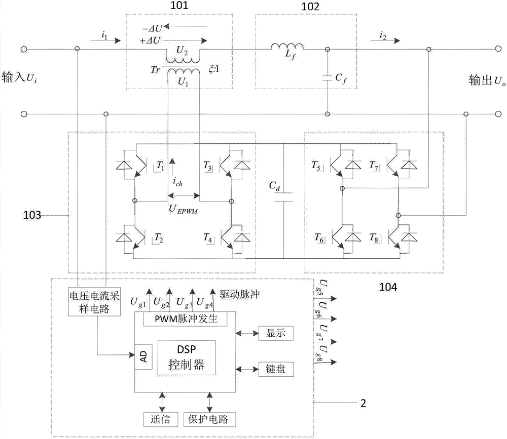
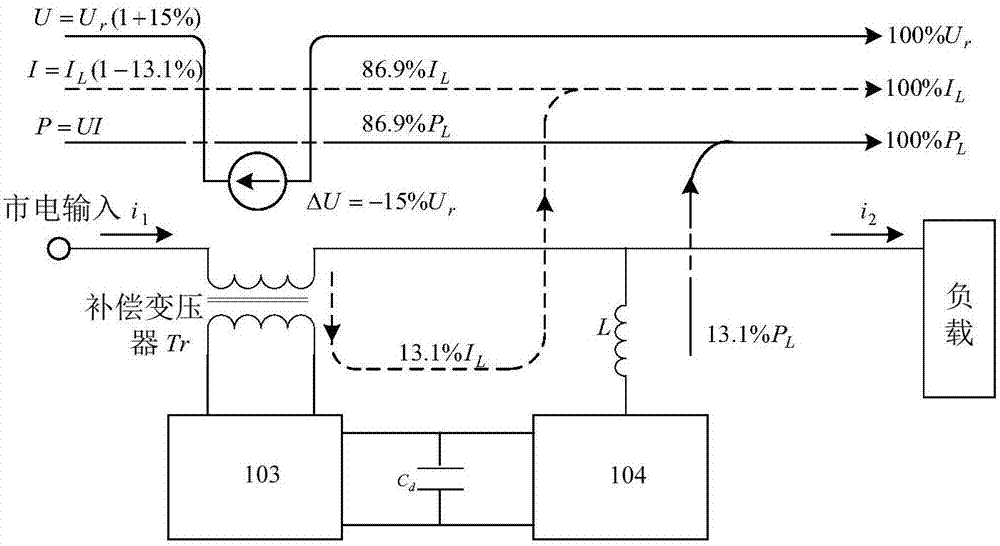
[0042] Such as figure 1 As shown, this embodiment provides a high-performance bidirectional dynamic voltage regulation device, including a main regulation circuit and a DSP control circuit 2, the main regulation circuit is connected between the power grid and the load, and includes a first PWM converter 103, a second PWM Converter 104, series compensation transformer 101 and sine wave filter 102, the first PWM converter 103 realizes the inflow and outflow control of grid energy under the control of DSP control circuit 2; d It is connected in parallel wi...


PUM


Abstract

The invention relates to a bidirectional dynamic voltage adjusting device. The bidirectional dynamic voltage adjusting device comprises an adjusting main circuit and a DSP control circuit, and the adjusting main circuit is connected between a power grid and a load. The bidirectional dynamic voltage adjusting device comprises a first PWM converter, which is used for inflow outflow control of power grid energy; a second PWM converter, which is parallely connected with the first PWM converter by an energy storage capacitor, and is used to realize inflow outflow control of load energy under control of a DSP control circuit; a serial connection compensation transformer; a sinusoidal wave filter, which is serially connected between the serial connection compensation transformer and the load, and is used to realize filtering of high frequency pulses. The primary side of the serial connection compensation transformer is connected with the first PWM converter, and the secondary side of the serial connection compensation transformer is directly serially connected with the power grid, and voltage drop and isolation are realized, and therefore the forward compensation or the backward compensation of the load voltage is realized under the control of the DSP control circuit. Compared with the prior art, advantages of a conventional mechanical type on-load voltage regulation transformer and a contactless thyristor on-load voltage regulation device are provided, and the inherent disadvantages thereof are overcome, and good performance is provided.

Description

technical field [0001] The invention relates to a grid voltage control device, in particular to a bidirectional dynamic voltage regulation device. Background technique [0002] As the power capacity of the power grid voltage changes at any time, the primary side voltage of the distribution transformer fluctuates greatly, resulting in unstable voltage on the secondary side of the distribution transformer, thereby affecting the quality of power consumption of users. Although the voltage drop is not as serious as the voltage interruption, it occurs more frequently. The voltage interruption is limited to a certain area or area, but the voltage drop can be caused by a fault in the transmission system hundreds of kilometers away, which causes damage to sensitive loads. The hazard is the same as that of a voltage interruption, or even more serious. Although the duration of the voltage drop is short, the widely distributed sensitive load has a significant impact on industrial produ...

Claims


Application Information

Patent Timeline
Patent Type & Authority Applications(China)
IPC IPC(8): H02J3/12
CPCH02J3/12
Inventor 江友华熊妮石伟刘雪莹伦恒星吴琦娜瞿殿桂周鼎
Owner SHANGHAI UNIVERSITY OF ELECTRIC POWER
Learn More