
Bionic stress sensing structure and formation method thereof

A bionic and conductive ink technology, applied in the field of strain sensing, can solve the problems of low cost, complicated preparation process, poor stability of synthesis process, etc.

Active Publication Date: 2017-07-18
JILIN UNIV
View PDF4 Cites 21 Cited by
  • Summary
  • Abstract
  • Description
  • Claims
  • Application Information

AI Technical Summary

Problems solved by technology

Metal sheet-type strain gauges with length changes have small length changes and small resistance changes during straining, so the strain detection range is small, and their gage factors (gauge factor, GF) are generally not high, ranging from 1.5 to 10. Within; new material strain sensors represented by metal nanoparticles or carbon nanotubes, graphene, etc., because their substrates are mostly flexible materials, the strain range is large and the sensitivity coefficient is high, but noble metal nanoparticles, carbon nanotubes or graphene materials The cost is high, the synthesis of the material is complicated, and the stability of the synthesis process is not good; the strain sensing structure of the micro-nano structure type is processed by photolithography technology, and the process reliability is good, but the manufacturing cost is high and the preparation process is complicated; in addition, The growth of the dendritic structure of nanowires is random, and it is difficult to control the parameters

Method used


Image

  • Bionic stress sensing structure and formation method thereof
  • Bionic stress sensing structure and formation method thereof
  • Bionic stress sensing structure and formation method thereof

Examples


Embodiment Construction

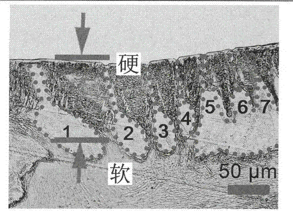
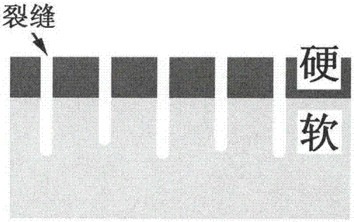
[0031] Such as figure 1 As shown, according to the inspiration of the slice structure of the scorpion crack receptor, the following figure 2 The bionic strain sensing structure on the paper substrate 1 is shown. figure 1 In the middle, the arrow mark is the hard chitin shell on the surface of the scorpion, and the soft subcutaneous tissue below the scorpion. The hard chitin shell is divided by the 1-7 cracks marked in the figure, forming a parallel crack belt structure. The bionic strain sensing structure inspired by this is such as figure 2 As shown, the upper layer is a dense and hard conductive layer adhered to a softer paper substrate 1. At the same time, there are multiple parallel cracks on the conductive layer, forming a strain sensing structure similar to the scorpion crack receptor structure. Its structure is characterized by printing and processing a hard conductive layer containing multiple parallel cracks (crack bands) on a soft base material (paper base layer), wh...


PUM


Abstract

The invention discloses a bionic stress sensing structure and a formation method thereof. According to the bionic stress sensing structure, a conducting ink layer with strip-shaped parallel slit bands is formed on a paper substrate. The conducting ink layer is compact and rigid while the paper substrate is porous and soft. The formation method of the bionic stress sensing structure includes printing a layer of conducting ink on the paper substrate, wherein the conducting ink forms the dry conducting ink layer which is compact and rigid after drying up; and bending the paper substrate so as to make the dry conducting ink layer to break in the bending process. In this way, a plurality of slits are formed in the dry conducting ink layer and the slits form the slit band bionic structure. The dry conducting ink layer becomes the conducting ink layer with the strip-shaped slit bands, so that the bionic stress sensing structure is formed. When the paper substrate is stressed and deformation occurs, the contact degree of the slit walls of the strip-shaped slits of the slit band bionic structure changes, so that the resistance of the conducting ink layer varies. Therefore, the stress sensing function is achieved.

Description

Technical field [0001] The invention relates to the field of strain sensing, in particular to a bionic strain sensing structure and a forming method thereof. Specifically, it relates to a method for preparing a biomimetic strain sensing structure by printing on a paper substrate. Brush the conductive coating on the surface of the paper substrate, and form a strip-shaped parallel crack zone after bending and breaking, forming a specific bionic crack structure. When the paper substrate is strained after being stressed, the crack width changes, that is, the contact degree of the crack wall changes, resulting in a change in its overall resistance, that is, a piezoresistive phenomenon is generated, and the strain sensing function is realized. The prepared strain sensing structure is a bionic structure inspired by scorpion vibration perception, and the bionic model is derived from the slit receptor of scorpion vibration perception. Background technique [0002] Sensors for strain mea...

Claims


Application Information

Patent Timeline
IPC IPC(8): G01B7/16
CPCG01B7/20
Inventor 韩志武宋洪烈张俊秋张卡杨明康刘林鹏王可军陈道兵牛士超朱斌侯涛
Owner JILIN UNIV
Learn More