
Heating supply system hydraulic equilibrium model prediction control method and system

A model predictive control and heating system technology, applied in heating systems, heating methods, household heating, etc., can solve problems such as low efficiency and high technical requirements for operating personnel

Active Publication Date: 2017-07-18
CHANGZHOU ENGIPOWER TECH
View PDF3 Cites 27 Cited by
  • Summary
  • Abstract
  • Description
  • Claims
  • Application Information

AI Technical Summary

Problems solved by technology

In the manual adjustment mode, for a large number of valves or water pumps, every time you adjust the opening of a valve or the operating frequency of a water pump, you need to wait for the system to run stably, and then make subsequent adjustments based on the adjustment effect. The repeated calibration process of readjustment is inefficient and requires high technical level of operating personnel

Method used


Image

  • Heating supply system hydraulic equilibrium model prediction control method and system
  • Heating supply system hydraulic equilibrium model prediction control method and system
  • Heating supply system hydraulic equilibrium model prediction control method and system

Examples


Embodiment 1

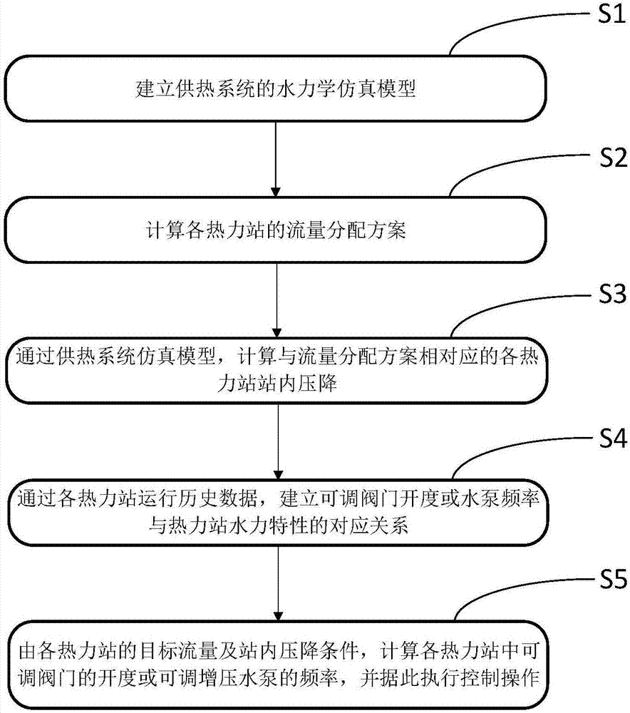
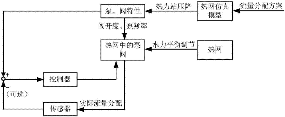
[0091] combine figure 1 and figure 2 , the model predictive control method of the hydraulic balance adjustment of the heating system of the present invention, specifically comprises the following steps:

[0092] Step S1, establishing a hydraulic simulation model of the heating system;

[0093] Step S2, calculating the flow distribution scheme of each thermal station;

[0094] Step S3, through the simulation model of the heating system, calculate the pressure drop in each heating station corresponding to the flow distribution scheme;

[0095] Step S4, establish the corresponding relationship between the adjustable valve opening or water pump frequency and the hydraulic characteristics of the thermal station through the operation history data of each thermal station; and

[0096] Step S5, calculate the opening of the adjustable valve or the frequency of the adjustable booster pump in each thermal station based on the target flow rate of each thermal station and the pressure ...

Embodiment 2

[0196] On the basis of Embodiment 1, Embodiment 2 provides a hydraulic balance control system for a heating system, including:

[0197] The model building module is used to establish the hydraulic simulation model of the heating system;

[0198] The flow distribution calculation module calculates the flow distribution scheme of each thermal station;

[0199] The pressure drop calculation module in the thermal station calculates the pressure drop in each thermal station corresponding to the flow distribution scheme through the simulation model of the heating system.

[0200]The hydraulic balance control system of the heating system also includes: a valve opening operating characteristic model and a water pump operating characteristic model building module, and through the valve opening operating characteristic model and the water pump operating characteristic model, the adjustment characteristic curve of the valve or water pump is obtained, namely According to the current flow...


PUM


Abstract

The invention relates to a heating supply system hydraulic equilibrium model prediction control method and system. The model prediction control method comprises the following steps that S1, a heating supply system hydraulics simulation model is built; S2, flow distribution schemes of all heating stations are calculated; S3, through the heating supply system hydraulics simulation model, in-station pressure drop of all heating stations corresponding to the flow distribution schemes is calculated; S4, through all heating station running historical data, the congruent relationship between the adjustable valve opening degree or water pump frequency and the heating station hydraulic characteristic is built; and S5, according to target flow and in-station pressure drop conditions of all heating stations, the adjustable valve opening degree or adjustable booster pump frequency in all heating stations are calculated, and control operation is accordingly executed.

Description

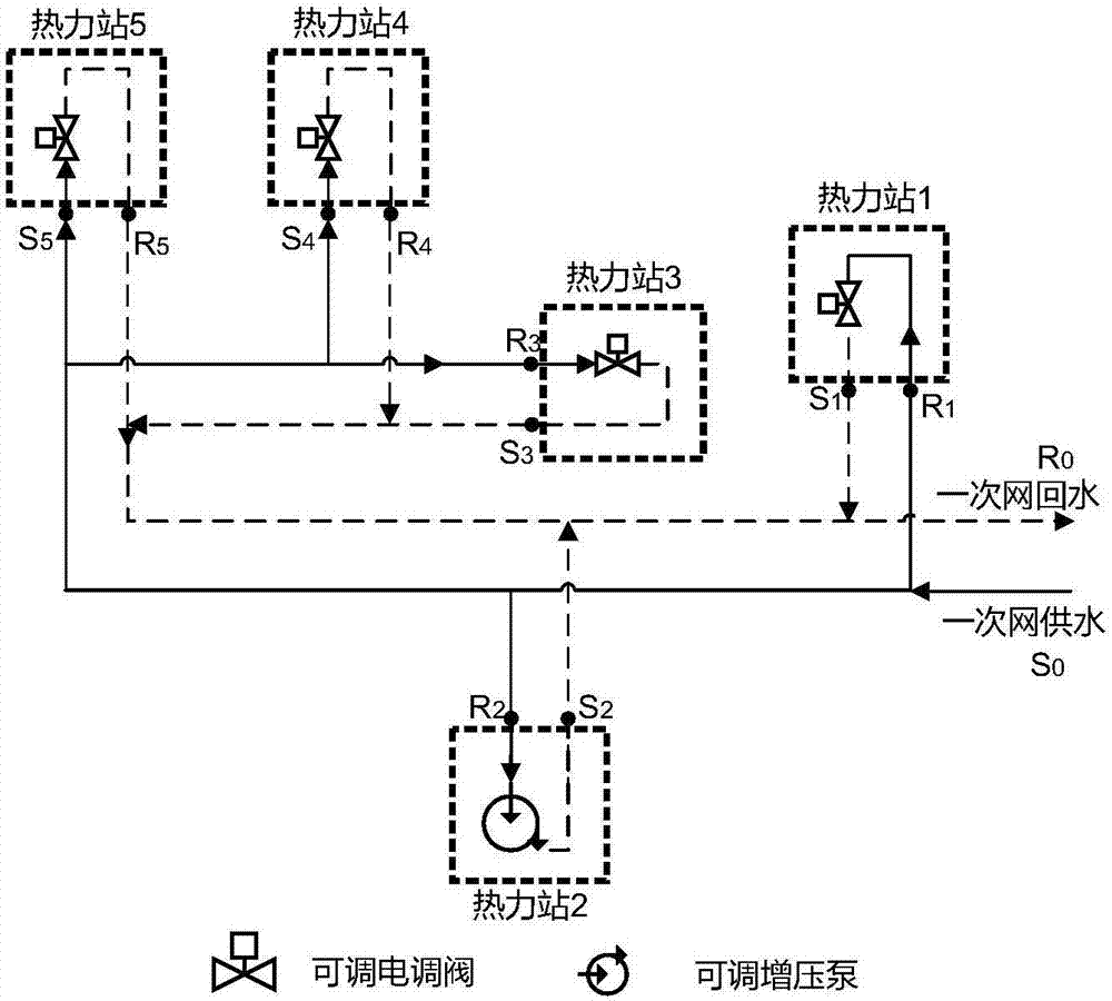
technical field [0001] The invention belongs to the field of advanced control of heating systems, and in particular relates to a method and system for model predictive control of adjustable valves or adjustable water pumps in multiple thermal stations in the system in order to realize the hydraulic balance of the heating system. Background technique [0002] The heating system produces high-temperature hot water in the heat source plant and drives the hot water to circulate in the primary pipe network to deliver heat energy to geographically distributed heat stations. During the transportation process, the on-demand distribution of hot water flow between the thermal stations is realized by adjusting the valve decompression or pump boosting in each thermal station in the system, that is, to maintain hydraulic balance. At present, the automatic control method of the hydraulic balance of the heating system mainly tracks the deviation between the temperature of the supply and re...

Claims


Application Information

Patent Timeline
IPC IPC(8): F24D19/10
CPCF24D19/1012F24D19/1015F24D2220/02
Inventor 方大俊董瑞郝静麒
Owner CHANGZHOU ENGIPOWER TECH
Learn More