
Facility and method jointly performing the compression of acidic gases from the hydroconversion or hydrotreating unit and of the tail gas from the catalytic cracking unit

A hydroconversion and catalytic cracking technology, applied in catalytic cracking, effluent separation, hydrotreating processes, etc., can solve the problem of acid gas not being removed, and achieve the effect of low marginal cost

Active Publication Date: 2017-07-18
AXENS SA
View PDF4 Cites 1 Cited by
  • Summary
  • Abstract
  • Description
  • Claims
  • Application Information

AI Technical Summary

Problems solved by technology

However, in this system acid gases are not removed upstream of the main separation operation

Method used


Image

  • Facility and method jointly performing the compression of acidic gases from the hydroconversion or hydrotreating unit and of the tail gas from the catalytic cracking unit
  • Facility and method jointly performing the compression of acidic gases from the hydroconversion or hydrotreating unit and of the tail gas from the catalytic cracking unit
  • Facility and method jointly performing the compression of acidic gases from the hydroconversion or hydrotreating unit and of the tail gas from the catalytic cracking unit

Examples


Embodiment

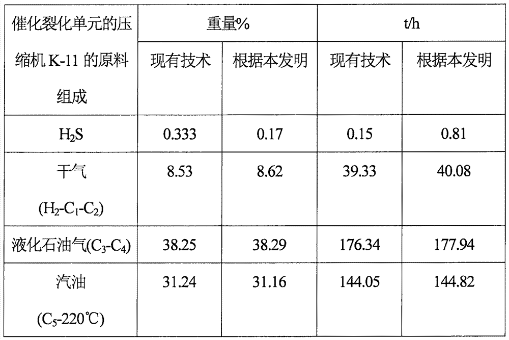
[0093] Table 1 below shows a system according to the prior art, i.e. with a compressor for the top gas of the main fractionation column C-1, and according to the invention, i.e. with only compression of the cracked gas for the catalytic cracking unit R-11 The results obtained for machine K-11, both of which also treated the top gas of fractionation column C-1.

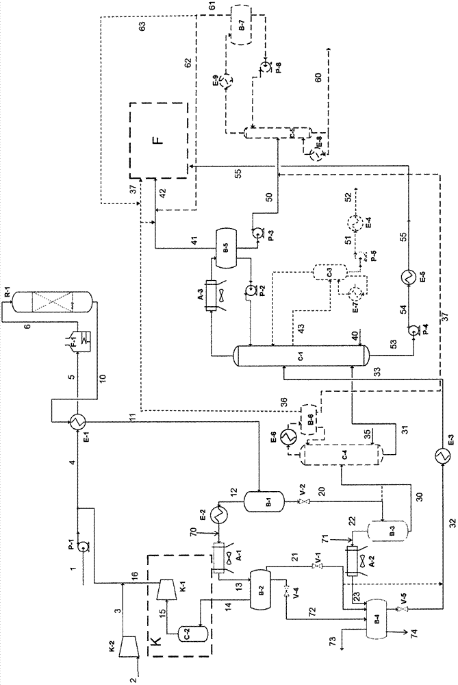
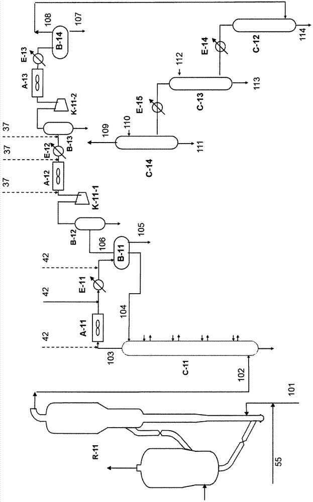
[0094] An embodiment according to the invention corresponds to figure 1 and figure 2 layout without the optional towers C-3, C-4, C-5 and figure 1 Corresponding segments indicated by dotted lines in .

[0095] According to the layout of the invention, the top compressor of the main fractionator C-1 of the hydroconversion or hydrotreatment section R-1 is suppressed due to the integration with the recovery compressor K-11 for the gaseous effluent of the catalytic cracking unit .

[0096] Due to the additional stream 42, the increase in the total flow at the inlet of the compressor K-11 of the catalytic cracking sect...


PUM


Abstract

The invention concerns an installation and a process which jointly implement compression of the acid gases from the hydroconversion or hydrotreatment unit and that of the gaseous effluents from the catalytic cracking unit.

Description

technical field [0001] The present invention relates to the field of processes for hydroconversion of atmospheric or vacuum residues, or vacuum gas oils or distillates, or processes for hydrotreating vacuum gas oils or distillates. Conventional hydroconversion or hydrotreating processes include a stage for fractional distillation of the effluent from the reaction stage, which primarily achieves two objectives, removal of H 2 S and light hydrocarbons and products of the main fractionation unit. Remove H 2 S and light hydrocarbons lead to the production of acid gases which must then be cleaned before being used as fuel gas. Description of drawings [0002] figure 1 A schematic diagram showing hydrotreating or hydroconversion reaction section R-1, along with main fractionation column C-1 and the different separator vessels identified as B-1 to B-5, is shown. R-1 includes a section for fractional distillation of the reaction effluent. [0003] exist figure 1 Three optional...

Claims


Application Information

Patent Timeline
Patent Type & Authority Applications(China)
IPC IPC(8): C10G67/00
CPCC10G67/00C10G2300/202C10G2300/207B01D3/4216C10G11/18C10G45/02C10G47/00C10G49/22C10G69/04C10G2300/1074C10G2300/1077C10G7/00C10G11/00
Inventor O·拉热内斯N·朗贝尔J·弗雷孔J·皮古里埃
Owner AXENS SA
Learn More