
Dual-floater direct-drive type wave power generation system based on speed-increasing type linear permanent magnet generator

A permanent magnet generator and wave power generation technology, which is applied to ocean energy power generation, engine components, machines/engines, etc., can solve the problems of large volume and mass of generators, difficulties in installation, commissioning and maintenance, and reduced system efficiency, so as to achieve energy Capturing and energy conversion functions, reducing the cost of manufacturing and the complexity of installation and debugging, and the effect of high conversion efficiency

Inactive Publication Date: 2017-07-14
SOUTHEAST UNIV
View PDF4 Cites 5 Cited by
  • Summary
  • Abstract
  • Description
  • Claims
  • Application Information

AI Technical Summary

Problems solved by technology

However, due to the relatively slow vibration speed of waves up and down, no matter whether a rotary motor or a linear motor is used, the volume and mass of the generator are generally large, which will bring a series of problems such as high manufacturing cost and difficult installation, commissioning and maintenance; if Using a traditional gearbox or hydraulic system to increase the speed to increase the speed of the generator mover will inevitably lead to problems such as reduced overall system efficiency and complicated maintenance.

Method used


Image

  • Dual-floater direct-drive type wave power generation system based on speed-increasing type linear permanent magnet generator
  • Dual-floater direct-drive type wave power generation system based on speed-increasing type linear permanent magnet generator

Examples


Embodiment Construction

[0038] The present invention will be further described below in conjunction with embodiment and accompanying drawing.

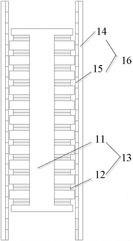
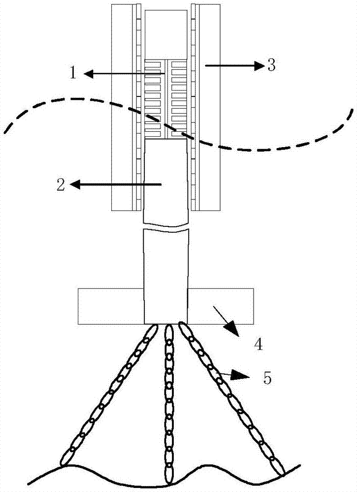
[0039] The direct-drive wave power generation system of the present invention includes a speed-increasing linear permanent magnet generator 1, an inner buoy 2 and an outer buoy 3, a damping disc 4, and an anchor chain 5; the speed-increasing linear permanent magnet generator 1 includes The stator 13 and the mover 16; the generator stator 13 is composed of the stator core 11 and the armature winding 12; the generator mover 16 is composed of the mover core 14 and the mover arranged in a surface-mounted or embedded manner along the inner surface of the mover core 14 Sub permanent magnet 15 forms;

[0040] The stator core 11 and armature winding 12 of the speed-increasing linear permanent magnet generator 1 are installed inside the inner buoy 2; 15 installed inside the outer buoy 3;

[0041] The invention adopts a speed-increasing linear permanent magnet genera...


PUM


Abstract

The invention discloses a dual-floater direct-drive type wave power generation system based on a speed-increasing type linear permanent magnet generator. The dual-floater direct-drive type wave power generation system comprises the speed-increasing type linear permanent magnet generator, an inner floating cylinder, an outer floating cylinder, a damping plate, anchor chains and the like; the whole set of the apparatus adopts a dual-floater structure, and is fixed on the seafloor through the anchor chains to form a floating type system; the inner floating cylinder and a stator of the speed-increasing type linear permanent magnet generator are connected integrally; a stator iron core and armature windings of the motor are mounted in the inner floating cylinder; the outer floating cylinder and a mover of the speed-increasing type linear permanent magnet generator are connected integrally; the outer floating cylinder is arranged outside the inner floating cylinder in a sleeving manner; and the damping plate provides enough buoyancy force to maintain a circular rod which is connected with the stator at a static state. The wave power generation system based on the speed-increasing type linear permanent magnet generator provided by the invention has the advantages of no need of an extra huge speed increasing apparatus, relatively small size, high energy capture and power generation efficiency, and convenience in designing, debugging and maintaining of an electrical control system by virtue of the overall floating suspension structure, and the like.

Description

technical field [0001] The invention relates to a device for generating electricity from wave energy by comprehensively utilizing linear magnetic gears and permanent magnet linear motors. Background technique [0002] Since the 1970s, with the decrease of biochemical energy and the aggravation of environmental pollution, people are increasingly favoring non-polluting, clean and sustainable renewable energy in terms of energy intake and application. Wave energy is an inexhaustible renewable energy. Compared with wind energy and solar energy, wave energy has the advantages of high power density and strong predictability, and has attracted the attention of experts and scholars at home and abroad. As a large ocean country, my country has a coastline of more than 18,000 kilometers and an island coastline of 14,000 kilometers. It is rich in wave energy resources. According to estimates from China's coastal marine observation stations, the theoretical average annual wave power alon...

Claims


Application Information

Patent Timeline
IPC IPC(8): H02K35/02H02K7/18F03B13/18
CPCF03B13/1845H02K7/1876H02K35/02Y02E10/30
Inventor 余海涛封宁君胡敏强施振川仲伟波刘小梅
Owner SOUTHEAST UNIV
Learn More