
Charging station and charging station system

A charging station, charge and discharge management technology, applied in battery circuit devices, collectors, electric vehicles, etc., can solve the problems of high panel temperature, unsatisfactory solar conversion efficiency, and lower solar conversion efficiency, and achieve good efficiency. Effect

Inactive Publication Date: 2017-07-14
石晋方
View PDF7 Cites 0 Cited by
  • Summary
  • Abstract
  • Description
  • Claims
  • Application Information

AI Technical Summary

Problems solved by technology

[0007] Solar panels absorb the light energy of the sun and convert it into electricity. The best way to implement it is to have a smooth light-receiving surface. However, the road surface must have a certain degree of friction and cannot reflect light to affect driving vision. Therefore, the above-mentioned solar tiles must be In addition, it is treated as a rough and uneven surface, but this will reduce its solar conversion efficiency
At the same time, the panel temperature of the solar panel rises after being exposed to the sun. If the ground temperature is also high, the panel temperature will remain high due to the inability to dissipate heat. Generally, the efficiency of a solar panel is based on the panel surface temperature of 25 degrees Celsius. , the power generation efficiency will be reduced by 0.5%. Taking the temperature of the solar panel in summer as an example when the temperature rises to 70 degrees Celsius, the efficiency will be reduced by 22.5%. The conversion efficiency of solar energy at this high temperature is not ideal.

Method used


Image

  • Charging station and charging station system

Examples


no. 1 example

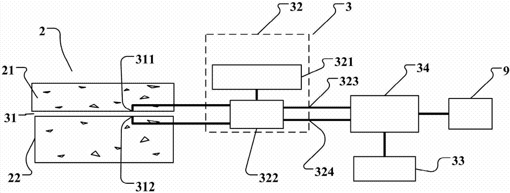
[0041] refer to figure 1 , the first embodiment of the present invention is a charging station 3, which is arranged on a road 2 for charging a load 9. The road 2 includes an upper layer 21 and a lower layer 22, between the upper layer 21 and the lower layer 22, There is a temperature difference due to solar radiation and the material properties of the road. The charging station 3 is used to charge the load 9, wherein the load 9 can be various rechargeable and dischargeable batteries, especially batteries of electric motorcycles or electric vehicles.

[0042] The road 2 includes an upper layer 21 and a lower layer 22, wherein the upper layer 21 and the lower layer 22 can choose different materials according to the application requirements of the road 2, for example, the upper layer 21 can be asphalt, a mixture of crushed stones, and the lower layer 22 can be It is the main body of artificially manufactured roadbed or natural earth and stone.

[0043] The charging station 3 in...


PUM


Abstract

The invention discloses a charging station and a charging station system. The charging station is arranged on a road 2 and used for charging a load 9; the road 2 comprises an upper layer 21 and a lower layer 22; the charging station 3 comprises a thermoelectric conversion element 31, a power storage unit 33 and a charging-discharging management unit 34; the thermoelectric conversion element 31 is arranged between the upper layer 21 and the lower layer 22 of the road 2 and used for converting the temperature difference between the upper layer 21 and the lower layer 22 into electric energy to be output; the power storage unit 33 is used for storing electric energy; and the charging-discharging management unit 34 is electrically connected to the power storage unit 33 and the thermoelectric conversion element 31 to receive the electric energy generated by the thermoelectric conversion element 31 and to store the electric energy in the power storage unit 33, and the charging-discharging management unit 34 is further electrically connected to the load 9 for charging the load 9. Therefore, solar energy on the road can be utilized properly, without affecting due friction coefficient of the road surface or causing unnecessary reflect light, and without being affected by sunshine or high ground surface temperature, and high efficiency is achieved.

Description

[0001] 【Technical field】 [0002] The invention relates to power generation, power transformation or power distribution technology, in particular to a power supply or power distribution circuit system and an electric energy storage system. [0003] 【Background technique】 [0004] In recent years, the pursuit of pure energy has become one of the main energy development goals. For example, the US government plans to lay solar bricks on roads for power generation. [0005] In the prior art, Chinese mainland patent CN200710189753.1 discloses a solar power plant on traffic roads, using the space resources on both sides of the roadbed or the space resources in the middle of the road to install solar panels to build a solar power plant, which can be integrated into the power grid or become independent The power network supplies power to form a green energy base. Lay solar panels on both sides of highways or ordinary roads or railways, arrange solar panels in a scientific way, and con...

Claims


Application Information

Patent Timeline
Patent Type & Authority Applications(China)
IPC IPC(8): H02J7/32
CPCH02J7/32H02J7/0034
Inventor 石晋方
Owner 石晋方
Learn More