
A semi-automatic electric cooking pot

A semi-automatic, electric heating technology, applied in the direction of cooking utensils, electric heating devices, vessels with integrated electric heating devices, etc., can solve the problems of unfriendly menu configuration mode, complex hardware and software parts of automatic electric heating cooking devices, and high cost

Active Publication Date: 2018-10-19
临沂威尔森新型材料有限公司
View PDF6 Cites 0 Cited by
  • Summary
  • Abstract
  • Description
  • Claims
  • Application Information

AI Technical Summary

Problems solved by technology

[0002] At present, in our country's existing automatic cooking pot technology, some are based on traditional cooking methods and steps, design and manufacture various automatic mechanical devices that simulate manual operations, and some are based on predetermined computer programs, with selected menu modes, Precise control of cooking temperature and time to realize automatic electric heating cooking, their disadvantages are: the hardware and software parts of various automatic electric heating cooking devices are relatively complicated, the various menu configuration modes can only be formatted and cannot be humanized, the product cost is high, and promotion is difficult
The invention application with the application number "2016102859714" discloses a "smart lid-type semi-automatic electric cooking pot" that overcomes the above shortcomings, but it is still relatively complicated and expensive

Method used

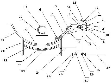
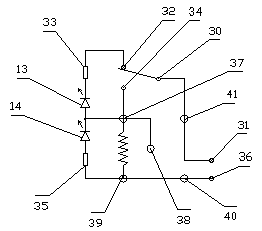

Image

  • A semi-automatic electric cooking pot
  • A semi-automatic electric cooking pot

Examples


Embodiment Construction

[0010] The present invention will be further described below in conjunction with the accompanying drawings and embodiments.

[0011] exist figure 1 , figure 2 Among them, the clip-type thermostat is provided with a clip bracket, and the clip bracket is like a usual clip, it is provided with an n-shaped upper bracket 1 and a u-shaped lower bracket 2, the lower end of the n-shaped upper bracket and the upper end of the u-shaped lower bracket are both There are front and rear shaft holes, the front and rear shaft holes of the n-type upper bracket and the front and rear shaft holes of the u-shaped lower bracket are jointly installed with a connecting shaft 3, and the middle part of the connecting shaft is provided with a clip spring 4, and the n-type upper The left end of the bracket is provided with a temperature-sensing head bracket 5, and the left end of the temperature-sensing head bracket is provided with a circlip groove, and the temperature-sensing head 6 is clamped in th...


PUM


Abstract

The invention discloses a semiautomatic electrothermal cooking pot, comprising a clip-type temperature controller, a stainless steel pot, an electric cooker and a power socket board, wherein the clip-type temperature controller is provided with a clip bracket; the front end of the clip bracket is provided with a temperature control switch; the left end of the temperature control switch is communicated with a capillary tube; the left end of the capillary tube is communicated with a temperature sensing head; the temperature sensing head is tightly clung to the lower right end of the stainless steel pot; a clip opening of the clip bracket is supported at the right end of the stainless steel pot. The pot disclosed by the invention has the advantages that a water level line at the bottom of the stainless steel pot is a sauce-reducing water level line during a cooking process; different water adding amount in the pot is controlled according to different food materials and cooking requirements, the water adding amount is in direct proportion to cooking time, the cooking time depends on the water adding amount, the cooking degree of cooked food depends on the cooking time, and the sauce-reducing degree of the cooked food depends on different pot bottom temperatures; the cooked food can reach an expected effect by means of flexibly and expertly mastering the water adding amount and the different pot bottom temperatures; after cooking, the electric cooker powers off automatically, the situation that the food is scorched due to oblivion is prevented, and the effects of saving time, labor and worry are achieved.

Description

technical field [0001] The invention relates to an automatic cooking pot, specifically a semi-automatic electric heating cooking pot. Background technique [0002] At present, in our country's existing automatic cooking pot technology, some are based on traditional cooking methods and steps, design and manufacture various automatic mechanical devices that simulate manual operations, and some are based on predetermined computer programs, with selected menu modes, Precise control of cooking temperature and time to realize automatic electric heating cooking, their disadvantages are: the hardware and software parts of various automatic electric heating cooking devices are relatively complicated, the various menu configuration modes can only be formatted and cannot be humanized, the product cost is high, and promotion is difficult . The invention application with the application number "2016102859714" discloses a "smart lid-type semi-automatic electric cooking pot" that overcome...

Claims


Application Information

Patent Timeline
Patent Type & Authority Patents(China)
IPC IPC(8): A47J27/00H05B1/02
CPCA47J27/004H05B1/0202H05B1/0266
Inventor 朱幕松
Owner 临沂威尔森新型材料有限公司
Learn More