Fast controllable polarizer for high-power electron cyclotron resonance heating system

An electron cyclotron resonance and heating system technology, applied in the microwave field, can solve the problems of low positioning accuracy, inability to efficiently couple, and the inability to use the electronic cyclotron vacuum transmission system, etc., to achieve high positioning accuracy and fast rotation control.

Active Publication Date: 2017-07-07
SOUTHWESTERN INST OF PHYSICS
View PDF8 Cites 11 Cited by
  • Summary
  • Abstract
  • Description
  • Claims
  • Application Information

AI Technical Summary

Problems solved by technology

[0004] In view of the above prior art, the present invention provides a fast controllable polarizer for a high-power electron cyclotron resonance heating system to solve the problem that the existing technology cannot be used in the electron cyclotron vacuum transmission system, and the positioning accuracy can only be caused by manual operation. It is not high and cannot be automatically matched with the antenna to achieve high-efficiency coupling; the invention is also used to solve technical problems such as rapid rotation of the polarized mirror under vacuum conditions, high positioning accuracy and precise control of the rotation angle, so as to ensure the smoothness of the polarized mirror in the vacuum environment. , reliable and accurate rotation

Method used


Image

  • Fast controllable polarizer for high-power electron cyclotron resonance heating system
  • Fast controllable polarizer for high-power electron cyclotron resonance heating system
  • Fast controllable polarizer for high-power electron cyclotron resonance heating system

Examples


Embodiment Construction

[0055] The present invention will be described in detail below in conjunction with the accompanying drawings and specific embodiments.

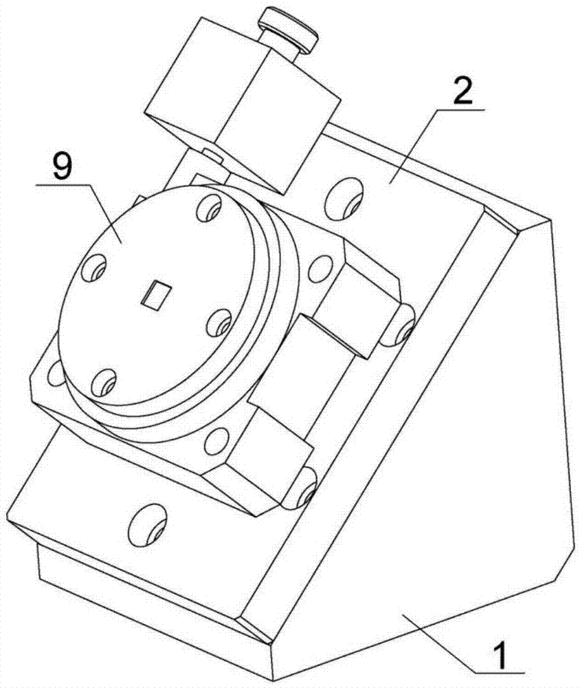
[0056] Such as Figure 1 to Figure 4 As shown, a fast controllable polarizer for a high-power electron cyclotron resonance heating system of the present invention includes: a microwave reversing elbow 1, a mounting substrate 2, a polarizing mirror 3, a static sealing O-ring 4, and a dynamic sealing O-ring Ring 5, supporting bearing 6, bearing seat 7, rotating shaft 8, rotating platform 9, coupling 10, motor 11, emergency manual adjustment device 12, 13-turbine, 14-worm;

[0057] The microwave reversing elbow 1 is connected with the electronic cyclotron transmission system, and is used to transmit high-power microwaves to achieve 90-degree reversing of the microwave transmission direction; comprehensively considering the loss of the reversing elbow, the microwave reversing elbow 1 is integrated type reversing elbow, that is, the input and out...


PUM


Abstract

The invention belongs to the field of microwave technologies, and specifically relates to a fast controllable polarizer for a high-power electron cyclotron resonance heating system. The fast controllable polarizer comprises a microwave reversing bend, a mounting base plate, a polarization mirror, a polarization mirror rotating mechanism and a rotation driving mechanism, and is characterized in that the microwave reversing waveguide bend is used for transmitting high-power microwaves and realizing 90-degree reversing in transmission direction of the microwaves; the mounting base plate is used for positioning the polarization mirror, the polarization mirror rotating mechanism and the rotation driving mechanism on the microwave reversing bend; the polarization mirror is used for reflecting the microwaves and realizing changes in microwave polarization mode while rotating; the polarization mirror rotating mechanism is used for realizing rotation of the polarization mirror in a vacuum environment; and the rotation driving mechanism is used for realizing accurate positioning control and protection for rotation of the polarization mirror. The fast controllable polarizer is high in positioning accuracy and capable of being fast controlled remotely, can MW-magnitude long-pulse millimeter waves stably and efficiently, and can meet an arbitrary control requirement of the electron cyclotron system for the microwave polarization mode.

Description

technical field [0001] The invention belongs to the field of microwave technology, in particular to a rapidly controllable polarizer for a high-power electron cyclotron resonance heating system. Background technique [0002] In electron cyclotron resonance heating systems, microwaves reaching the resonant layer require specific microwave polarization forms to carry out ordinary (O) mode or extraordinary (X) mode heating. The ratio of O-mode and X-mode varies depending on the microwave polarization form and incident angle. When changing the plasma operating parameters or microwave incident angle, the microwave polarization form must be changed to achieve efficient coupling between the wave and the plasma. The microwave output by the wave source gyrotron is usually a linearly polarized wave. Generally, a polarizer needs to be used to change the polarization mode of the wave during the wave transmission process to obtain an elliptical polarized wave or a circular polarized wave...

Claims


Application Information

Patent Timeline
Patent Type & Authority Applications(China)
IPC IPC(8): H01P1/165H01P1/17H05B6/64
CPCH01P1/165H01P1/17H05B6/64
Inventor 黄梅陈罡宇夏冬辉银刚张峰
Owner SOUTHWESTERN INST OF PHYSICS
Why Eureka
Try Eureka