
all-optical trigger

An optical triggering and laser technology, applied in optics, optical bistable devices, etc., can solve the problems that bistable is not stable and controllable, and the speed of optical exchange is limited, and achieve low cost, easy integration, and low energy consumption. Effect

Active Publication Date: 2020-01-21
INST OF SEMICONDUCTORS - CHINESE ACAD OF SCI
View PDF4 Cites 0 Cited by
  • Summary
  • Abstract
  • Description
  • Claims
  • Application Information

AI Technical Summary

Problems solved by technology

The dual-region common cavity structure using the saturated absorption effect of the absorption region is the earliest proposed bistable semiconductor laser. However, because the light exchange speed of this structure is limited by the carrier relaxation time of the absorption region, the time for the signal light to turn off Usually on the order of nanoseconds
In contrast, the bistable laser based on mode competition uses the nonlinear gain saturation effect of the mode, and the carrier changes very little when the state changes, so it has a high switching speed. Bistable lasers are produced by competition between clockwise and counterclockwise modes, symmetric and antisymmetric modes, which have broad application prospects in high-speed digital communications and optical logic computing circuits. However, the bistable states of current bistable lasers are not not stable and controllable

Method used


Image

  • all-optical trigger
  • all-optical trigger
  • all-optical trigger

Examples


Embodiment

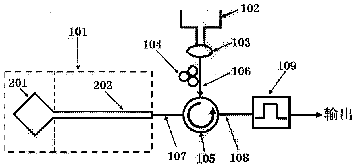
[0051] Such as figure 1 As shown, this embodiment proposes an all-optical trigger, including:

[0052] A coupled microcavity laser 101, the coupled microcavity laser is a room temperature continuous electrical injection laser, and its structure is formed by connecting a whispering gallery microcavity 201 with a Fabry-Perot cavity 202;

[0053] A trigger signal input terminal 102, which is used to input optical pulse signals of different wavelengths as setting set and reset reset signals, and its wavelength corresponds to the output light bistable wavelength of the coupled microcavity laser 101;

[0054] An optical beam combiner 103 for combining optical pulse signals of different wavelengths;

[0055] A polarization controller 104, whose input end is connected with the output end of the optical beam combiner 103, and is used for adjusting the polarization state of the optical pulse signal;

[0056] A fiber optic circulator 105 is a three-port structure, wherein the optical s...


PUM

PropertyMeasurementUnit
wavelengthaaaaaaaaaa

Abstract

An all-optical trigger comprises a coupled micro-cavity laser formed by an echo wall type micro-cavity and a Fabry-Perot cavity which are connected by an electrical isolation trench for emitting laser beams; a trigger signal input terminal for inputting optical pulse signals with different wavelengths; and an optical fiber circulator which is respectively connected with the coupled micro-cavity laser and the trigger signal input terminal, used for injecting the optical pulse signals to the coupled micro-cavity laser, and also used for outputting the laser beams emitted by the coupled micro-cavity laser. When the echo wall type micro-cavity is in a loss / gain state, the coupled micro-cavity laser is in an optical bistable / non-optical bistable state. Accordingly, through controlling gain and loss of the echo wall type micro-cavity, controllable output of the optical bistable state can be achieved; and the optical switching speed can be as high as several picoseconds.

Description

technical field [0001] The invention belongs to the field of semiconductor optoelectronic devices, in particular to an all-optical trigger. Background technique [0002] In order to meet the increasing demand for information, high-speed, high-capacity, low-power optical routing, optical switching, and optical transmission technologies have become the only way for the development of next-generation optical communication networks. As an optical logic element with memory function, the all-optical trigger is used to provide control signals for data storage, packet switching, and signal recovery and regeneration. It is the most basic processing unit in the all-optical signal processing system. , optical buffers, data packet switching nodes and other technologies have a wide range of applications. [0003] Optical bistability is an important means to realize optical flip-flops. It means that there are two stable optical output states under one input state, and the input and outpu...

Claims


Application Information

Patent Timeline
Patent Type & Authority Patents(China)
IPC IPC(8): G02F3/02
CPCG02F3/026
Inventor 马秀雯黄永箴杨跃德肖金龙翁海中王福丽汤敏
Owner INST OF SEMICONDUCTORS - CHINESE ACAD OF SCI
Learn More