Quantum imaging method and quantum imaging system
A quantum imaging and image technology, applied in the field of quantum imaging, can solve problems such as poor imaging effect
- Summary
- Abstract
- Description
- Claims
- Application Information
AI Technical Summary
Problems solved by technology
Method used
Image
Examples
Embodiment 1
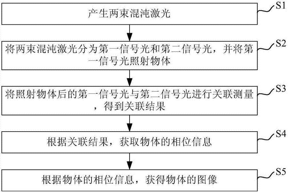
[0036] Please refer to figure 1 , this embodiment provides a quantum imaging method, including:
[0037] Step S1, generating two chaotic laser beams. Specifically, in this embodiment, there are two chaotic laser sources, and each laser source generates a beam of chaotic laser light respectively.
[0038] Step S2, dividing the two chaotic laser beams into first signal light and second signal light, and irradiating the object with the first signal light.
[0039] In this embodiment, two chaotic laser beams are irradiated on the first spectroscopic device respectively, and the two chaotic laser beams are entangled on the first spectroscopic device, and each chaotic laser beam has part of the light reflected and the other part of the light transmitted. , wherein the reflected light in the first chaotic laser and the transmitted light in the second chaotic laser form the first signal light, and the transmitted light in the first chaotic laser and the reflected light in the second...
Embodiment 2
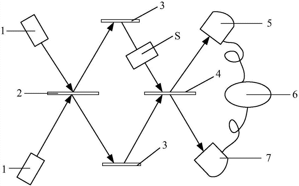
[0087] Please refer to figure 2 , this embodiment provides a quantum imaging system, including: a laser 1 , a first spectroscopic device 2 , an optical mirror 3 , a second spectroscopic device 4 , a first detection device 5 , a data processing device 6 and a second detection device 7 .
[0088] Laser 1 is used to generate two chaotic laser beams.
[0089] The first light splitting device 2 is used for splitting two beams of chaotic laser light into first signal light and second signal light.
[0090] The optical mirror 3 is used to reflect the first signal light, so that the first signal light irradiates the object S and then goes to the second spectroscopic device 4; it is used to reflect the second signal light, so that the second signal light goes to the second spectroscopic device 4. Two light splitters 4.
[0091] The second spectroscopic device 4 is used for correlating and measuring the second signal light and the first signal light after irradiating the object S to ...
Embodiment 3
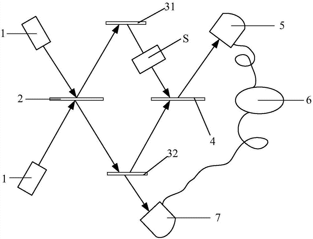
[0101] Please refer to image 3 , this embodiment provides a quantum imaging system, which has a similar structure to the quantum imaging system in Embodiment 2, the difference being that the optical mirror 3 includes: a first optical mirror 31 and a second optical mirror 32 .
[0102] The first optical mirror 31 is used to reflect the first signal light, so that the first signal light irradiates the object S and then goes to the second spectroscopic device 4 .
[0103] The second optical mirror 32 is used to reflect and transmit the second signal light, so that part of the second signal light goes to the second spectroscopic device 4 , and another part of the second signal light goes to the second detection device 7 .
[0104] In this embodiment, the first optical mirror 31 is made of a reflective material; the second optical mirror 32 is made of a material that can both transmit and reflect, so that the transmitted light in the second signal light can be deduced The informa...
PUM
 Abstract
Description
Claims
Application Information
 - R&D
- Intellectual Property
- Life Sciences
- Materials
- Tech Scout
- Unparalleled Data Quality
- Higher Quality Content
- 60% Fewer Hallucinations
Browse by: Latest US Patents, China's latest patents, Technical Efficacy Thesaurus, Application Domain, Technology Topic, Popular Technical Reports.
© 2025 PatSnap. All rights reserved.Legal|Privacy policy|Modern Slavery Act Transparency Statement|Sitemap|About US| Contact US: help@patsnap.com


