
Pipe rack prefabrication and assembly construction method

A construction method and prefabricated assembly technology, applied in artificial islands, water conservancy projects, infrastructure projects, etc., can solve the problems of difficult construction and large occupation of the construction site, and achieve the effect of small quantity

Inactive Publication Date: 2017-07-07
CHINA FIRST METALLURGICAL GROUP
View PDF4 Cites 7 Cited by
  • Summary
  • Abstract
  • Description
  • Claims
  • Application Information

AI Technical Summary

Problems solved by technology

However, the weight of the large-section pipe gallery will reach more than 100t in this length. In this case, the prefabrication, transportation and installation of the pipe gallery require super-large machinery, and the construction is difficult.
[0004] China Construction Group tried a new prefabricated construction method in Changsha and Yuanda, combining prefabricated structure and cast-in-situ construction, and achieved remarkable results in the on-site construction of large-scale pipe corridors. However, concrete pouring construction still needs to be carried out on site, and support and pouring are required. The plane occupation of the construction site is also relatively large

Method used


Image

  • Pipe rack prefabrication and assembly construction method
  • Pipe rack prefabrication and assembly construction method
  • Pipe rack prefabrication and assembly construction method

Examples


Embodiment Construction

[0044] In order to make the objectives, technical solutions and advantages of the present invention clearer, the following further describes the present invention in detail with reference to the accompanying drawings and embodiments. It should be understood that the specific embodiments described here are only used to explain the present invention, but not to limit the present invention.

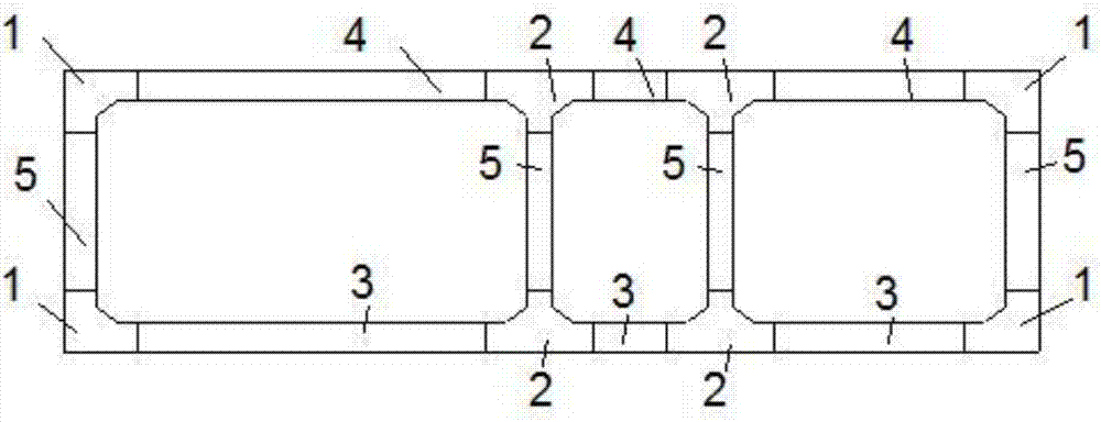
[0045] As attached figure 1 As shown, the decomposition design of the pre-assembled components of the pipe gallery is shown to form an exploded view of the sectional components of the pipe gallery.

[0046] The section of the pipe gallery is decomposed and designed for the pre-assembled structure, and the “L”-shaped corner beams are designed according to the structural forces of each component: 1: used for corners at the outer wall of the pipe gallery; “T”-shaped corner beams 2: used for pipes Tuck corners at the inner wall of the gallery; bottom plate member 3: used for the bottom of the pipe ga...


PUM


Abstract

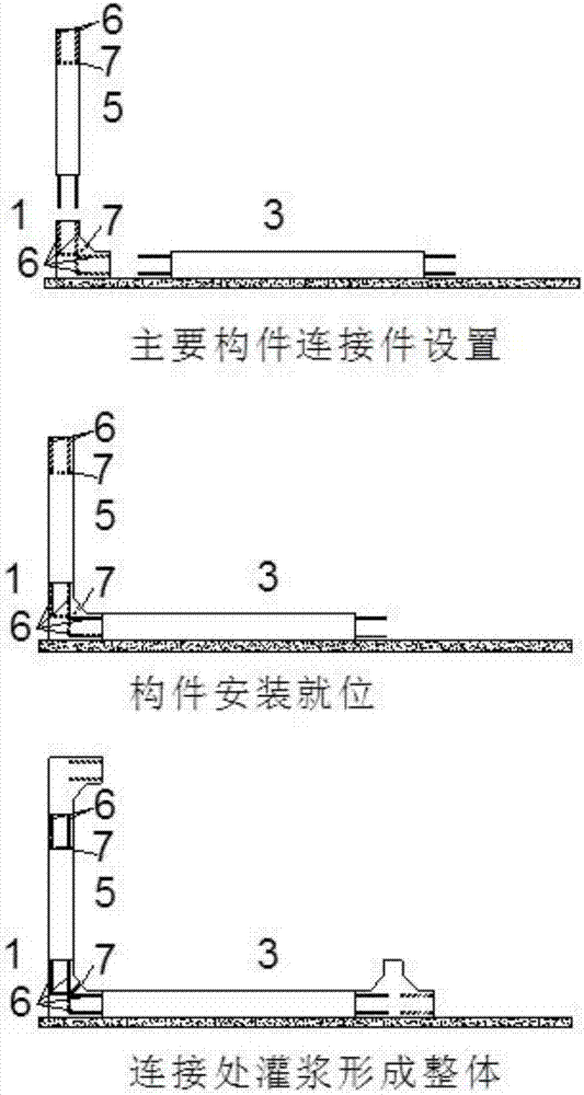
The invention discloses a pipe rack prefabrication and assembly construction method. The construction method comprises the following steps: a pipe rack is decomposed to different components; the components are manufactured and cured in a prefabrication factory; after a foundation pit in a construction site is excavated, a groove is inspected, and a cushion layer is arranged; a slide layer is arranged on the top surface of the cushion layer; beam plate components on a baseplate are lifted, and are placed in place from the middle to two sides of the baseplate; a prestressed steel strand is inserted through the baseplate for primary tightening; wallboard components are mounted to build a top plate support system; beam plate components on a top plate are mounted; a prestressed steel strand is inserted through the top plate for primary tightening; prestressed reinforcements of the baseplate and the top plate are tensioned to adjust the overall size of the pipe rack; and component connecting places and prestress reserved holes are closed through pressure grouting to finish assembly and construction of the section of pipe rack. A new large-section pipe rack construction scheme can provide a preassembly scheme to an ultralarge-section multi-cabin pipe rack. Compared with a traditional assembly scheme, the component weight is reduced, and the requirements on large machinery by the assembly construction are reduced.

Description

Technical field [0001] The invention relates to a building construction method, in particular to a pipe gallery prefabricated assembly construction method, and belongs to the technical field of construction engineering. Background technique [0002] In the construction of the underground comprehensive pipe gallery, the prefabricated pipe gallery is mostly used in small and medium sections. The construction adopts the open-cut assembly method. The concrete components are in the factory. [0003] For prefabrication, the quality of concrete components is easy to control, the construction speed is fast, and the construction area takes up a short time. Generally, the pre-assembly design of the pipe gallery is based on the overall section of the pipe gallery with a standard section of 2 to 2.5m. However, the weight of the large-section pipe gallery will reach more than 100t in this length. In this case, the prefabricated transportation and installation of the pipe gallery require super-...

Claims


Application Information

Patent Timeline
IPC IPC(8): E02D29/045
CPCE02D29/10
Inventor 吴云飞金钊张俊
Owner CHINA FIRST METALLURGICAL GROUP
Learn More