Fixing base with shock absorption function for smart battery on unmanned aerial vehicle

A technology of smart batteries and drones, applied in the field of drones, can solve problems such as unstable control of aircraft and gimbals, unstable flight conditions, and excitation of screen transmission

Pending Publication Date: 2017-07-07
广东省世纪南方科技有限公司
View PDF0 Cites 4 Cited by
  • Summary
  • Abstract
  • Description
  • Claims
  • Application Information

AI Technical Summary

Problems solved by technology

[0002] Many of the current UAV flight control modules and UAV gimbal mounting system modules have gyroscopes and accelerometers. Its ideal output is to only respond to changes in angular velocity, but in fact it is limited by design and technology. The gyroscope is also sensitive to acceleration. For the application of UAV aircraft, this indicator is particularly important, because the power system in the UAV aircraft, such as the motor and propeller, will bring strong vibration when cutting the air. Once the vibration is reduced If the control is not good, there will be a large acceleration during the flight, which will inevitably lead to changes in the output of the gyroscope, which will cause changes in the angle, and the motor will malfunction, and finally bring instability to the control of the aircraft and the gimbal.
Most of the current drones have a camera function. During the flight, due to the instability of the flight status of the drone, the vibration, mainly caused by other power systems or vibrations during the movement, will cause the entire camera system to shake. Or deflection, which affects the transmission of the returned picture and causes excitation, which causes the precision parts such as sensors on the aircraft to be affected by the surface quality. The posture is changed by swinging and vibrating, so the vibration reduction of the UAV carrier and the gimbal must meet high requirements for dynamics

Method used


Image

  • Fixing base with shock absorption function for smart battery on unmanned aerial vehicle
  • Fixing base with shock absorption function for smart battery on unmanned aerial vehicle
  • Fixing base with shock absorption function for smart battery on unmanned aerial vehicle

Examples


Embodiment 1

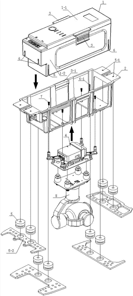
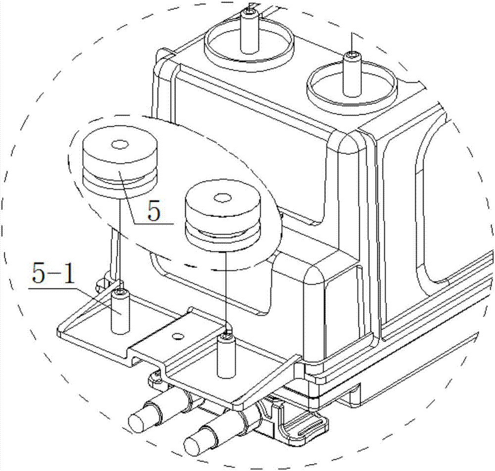
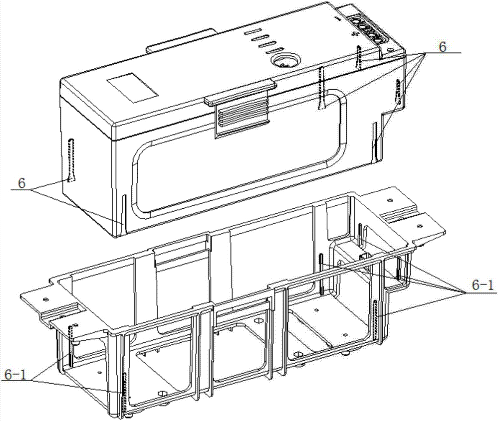
[0017] Such as Figure 1-Figure 4 As shown, a fixed seat for a smart battery with a vibration reduction function on a drone in this embodiment includes a smart battery 1, a smart battery holder 2, a smart battery fixing buckle 3, a flight control module group 4, and a Shock silicone rubber gasket 5, smart battery positioning concave guide groove 6, screw 7 and unmanned aerial vehicle platform mounting system module 8, it is characterized in that: described smart battery 1 comprises smart battery upper shell 1-1 and smart battery The lower casing 1-2, the smart battery upper casing 1-1 is provided with a smart battery fixing buckle 3, and the four sides of the smart battery lower casing 1-2 are provided with a smart battery positioning concave guide groove 6, The shock-absorbing silicone rubber gasket 5 includes a shock-absorbing gasket fixing column 5-1 and a fuselage fixing plate 5-2, the smart battery fixing buckle 3 includes a buckle fixing groove 3-1, and the smart battery...


PUM


Abstract

The invention discloses a fixing base with shock absorption function for a smart battery on an unmanned aerial vehicle. The fixing base comprises a smart battery, a smart battery holder, a smart battery fixing buckle, a flight control module group, a shock absorption silicone rubber gasket, smart battery positioning concave grooves and a screw. The fixing base is characterized in that the smart battery comprises a smart battery upper shell and a smart battery lower shell, the smart battery fixing buckle is arranged on the smart battery upper shell, and the smart battery positioning concave grooves are formed in the four edges of the smart battery lower shell. According to the fixing base with shock absorption function for the smart battery on the unmanned aerial vehicle, when the unmanned aerial vehicle flies, shock is isolated through the shock absorption silicone rubber gasket and an unmanned aerial vehicle body, so that transmission of shock is reduced or isolated, the shock brought by a power group and the shock brought due to various reasons in a flight are isolated through silicone rubber, so that the vibration frequency can be quickly attenuated to achieve the purpose of shock absorption, the principle lies in that the battery and the unmanned aerial vehicle body are subjected to shock absorption and isolation, and the self-weight of the battery is utilized to suppress the shock.

Description

technical field [0001] The invention relates to the field of unmanned aerial vehicles, in particular to a fixing seat for an intelligent battery with a vibration damping function on an unmanned aerial vehicle. Background technique [0002] Many of the current UAV flight control modules and UAV gimbal mounting system modules have gyroscopes and accelerometers. Its ideal output is to only respond to changes in angular velocity, but in fact it is limited by design and technology. The gyroscope is also sensitive to acceleration. For the application of UAV aircraft, this indicator is particularly important, because the power system in the UAV aircraft, such as the motor and propeller, will bring strong vibration when cutting the air. Once the vibration is reduced If the control is not good, there will be a large acceleration during the flight, which will inevitably lead to changes in the output of the gyroscope, which will cause angle changes, and the motor will malfunction, whic...

Claims


Application Information

Patent Timeline
IPC IPC(8): B64D47/00H01M2/10H01M50/20
CPCB64D47/00H01M50/20Y02E60/10
Inventor 邓世钱彭水立王浩涛熊杏林
Owner 广东省世纪南方科技有限公司
Why Eureka
Try Eureka