
Valve tappet cleaning component

A technology for cleaning components and valves, applied in cleaning methods and utensils, cleaning methods using liquids, chemical instruments and methods, etc., can solve the problems of reduced efficiency, time-consuming power consumption, low efficiency, etc., to avoid secondary cleaning, cleaning Fast and efficient, good cleaning effect

Inactive Publication Date: 2017-07-07
TIANJIN RUIPU TIANSHENG AUTO PARTS MFG
View PDF0 Cites 1 Cited by
  • Summary
  • Abstract
  • Description
  • Claims
  • Application Information

AI Technical Summary

Problems solved by technology

[0002] The valve lifter is a main component of the valve train, which can transmit the thrust of the cam to the push rod or the valve, and bear the lateral force exerted by the camshaft when it rotates. It is inevitable that it will be stained with oil and impurities during use. If it is not cleaned in time, it will affect the work of the valve lifter, and even affect the operation of the mechanical system. At present, the commonly used cleaning equipment for the valve lifter is an ultrasonic cleaning machine. The dirt on the tappets is removed, but the traditional cleaning baskets are mostly fixed and unidirectional, which may lead to incomplete cleaning of the valve tappets, and there is still oil in the valve tappets, which requires secondary or even multiple cleanings, which not only increases Increased cleaning workload, reduced efficiency, time-consuming power consumption, and increased costs
Therefore, the existing valve lifter cleaning equipment has the disadvantages of low efficiency, high cost, incomplete cleaning, etc.

Method used


Image

  • Valve tappet cleaning component

Examples


Embodiment Construction

[0019] The present invention will be described in detail below in conjunction with the accompanying drawings.

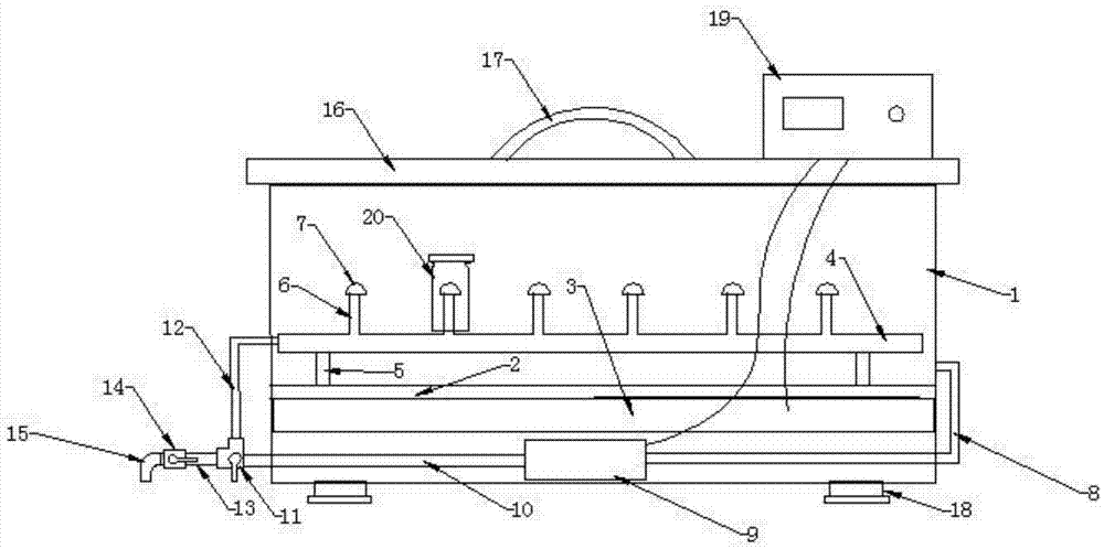
[0020] like figure 1 As shown, a valve tappet cleaning assembly of the present invention includes a casing 1, a waterproof board 2, an ultrasonic device 3, a water main pipe 4, a foot pad 5, a water spray pipe 6, a water spray head 7, a water outlet pipe 8, and a water pump 9 , return pipe 10, three-way valve 11, water inlet pipe 12, drain pipe 13, drain valve 14, drain faucet 15, cover 16, handle 17, cushioning pad 18, numerical control instrument 19.

[0021] The casing 1 is provided with a water main pipe 4 placed horizontally and closed at the right end. The main water pipe 4 is provided with six water spray pipes 6 perpendicular thereto. A waterproof board 2 fixed on the casing 1 is provided, and the main water pipe 4 is supported on the waterproof board 2 through feet 5 .

[0022] An ultrasonic device 3 is arranged under the waterproof board 2, and a water pu...


PUM


Abstract

The invention provides a valve tappet cleaning assembly, which includes a casing, a waterproof board, an ultrasonic device, a water main pipe, foot pads, a water spray pipe, a water spray head, a water outlet pipe, a water pump, a water return pipe, a three-way valve, a water inlet pipe, and a water discharge pipe. Pipe, drain valve, drain faucet, cover, numerical control instrument, there is a main water pipe inside the casing, a water spray pipe is provided on the main water pipe, a water spray head is provided on the top of the water spray pipe, and a waterproof board is provided directly below the main water pipe. The water pipe is supported on the waterproof board through the feet. There is an ultrasonic device under the waterproof board. There is a water pump under the ultrasonic device. The right side of the water pump is connected to the casing through the outlet pipe. They are respectively connected with the water inlet pipe and the drain pipe, the water inlet pipe is connected with the main water pipe, the left end of the drain pipe is provided with a drain tap, the drain tap is provided with a drain valve, the upper end of the casing is provided with a cover, and a numerical control instrument is provided on the cover. The invention has the beneficial effects of high efficiency, low cost and thorough cleaning.

Description

technical field [0001] The invention belongs to the technical field of valve lifter cleaning, in particular to a valve lifter cleaning assembly. Background technique [0002] The valve lifter is a main component of the valve train, which can transmit the thrust of the cam to the push rod or the valve, and bear the lateral force exerted by the camshaft when it rotates. It is inevitable that it will be stained with oil and impurities during use. If it is not cleaned in time, it will affect the work of the valve lifter, and even affect the operation of the mechanical system. At present, the commonly used cleaning equipment for the valve lifter is an ultrasonic cleaning machine. The dirt on the tappets is removed, but the traditional cleaning baskets are mostly fixed and unidirectional, which may lead to incomplete cleaning of the valve tappets, and there is still oil in the valve tappets, which requires secondary or even multiple cleanings, which not only increases It reduces ...

Claims


Application Information

Patent Timeline
Patent Type & Authority Applications(China)
IPC IPC(8): B08B3/12B08B3/02
CPCB08B3/12B08B3/02B08B2203/0258
Inventor 郭宗强
Owner TIANJIN RUIPU TIANSHENG AUTO PARTS MFG
Learn More