
Dry powder inhaler

A dry powder inhaler and carrier plate technology, used in inhalers, drug devices, other medical devices, etc., can solve the problems of influence of clean conditions, poor sealing, easy to cause pollution, etc., to reduce production and management costs, prevent Button offset, easy cleaning effect

Pending Publication Date: 2017-07-07
SUZHOU SINGMED MEDICAL DEVICE SCI & TECH LTD
View PDF7 Cites 17 Cited by
  • Summary
  • Abstract
  • Description
  • Claims
  • Application Information

AI Technical Summary

Problems solved by technology

Disadvantages of this type of powder inhaler: 1. The amount of powder delivered each time is unstable; 2. The sealing performance of this type of powder drug inhaler is poor, so the powder is easily affected by moisture in a relatively humid environment, which affects the expected effect; 3. The powder During the separation process in the storage, some powder will remain inside the powder drug inhaler, which will pollute the powder drug inhaler and cause certain harm to the user
This type of powder drug inhaler better guarantees the sealing of the powder; its disadvantages: 1. Poor repeatability, and there are differences in the delivery of the same powder drug inhaler to the patient before and after; 2. The inside of the powder drug inhaler will Residual drug powder will pollute the powder inhaler and cause certain harm to the user; 3. There will be powder residue in the blister, which will cause the performance of the powder to fail to achieve the expected effect;
The shortcoming of existing this type of product: one, the reliability of existing powder medicine inhaler is poor; Normal use; 2. The powder drug inhaler cannot be fully cleaned, which is easy to cause pollution; 3. The use is not humane enough, and the use is not convenient enough; the assembly process is complicated, the defective rate is high, and the manufacturing cost is high
Assembly is troublesome, from an economical point of view, this spindle is completely unnecessary
[0008] 2. A pair of transparent windows are used. The actual size of the window is restricted by the strength of the components and cannot be made very large. It is not suitable for patients to observe the internal situation. It is likely to cause patients to misjudge the internal situation and cause later stage When taking medicine, inhaling extra medicine or even dirty
Moreover, the main airflow of the capsule chamber is also connected to the lower shell cavity first, and then to the atmosphere, which leads to whether the airflow in the lower shell cavity is clean or not, which will affect the cleanliness of the two airflows
[0010] 4. In the current prior art, the capsule chamber is provided with two pointed points which can be oppositely moved with the spring to push the button. This button is extremely inconvenient to install on the capsule chamber. The capsule room is extremely inconvenient, and has not obtained good quality control conditions, and it may fall
[0011] 5. A hole smaller than 1mm is set on the bottom plate. The edge of this hole is very close to the capsule chamber, resulting in a weak structure of the part. Not only the product is easily damaged, but the mold is also easily damaged.
[0012] 6. There is a slit formed by a reduced width on the base plate close to the main shaft, resulting in a relatively weak base plate on this side of the main shaft

Method used


Image

  • Dry powder inhaler
  • Dry powder inhaler
  • Dry powder inhaler

Examples


Embodiment 1

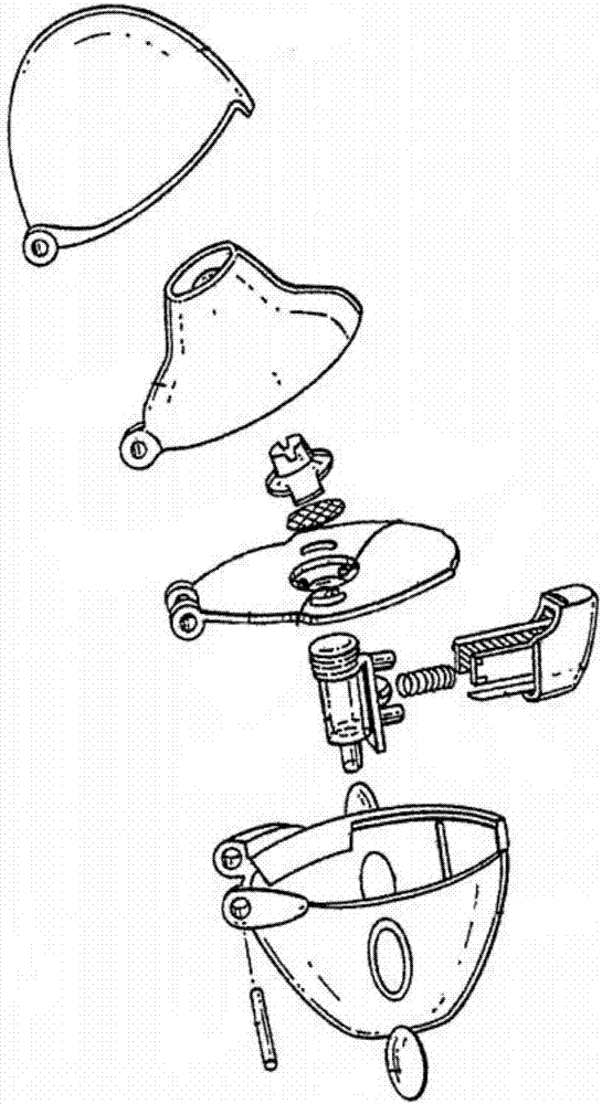
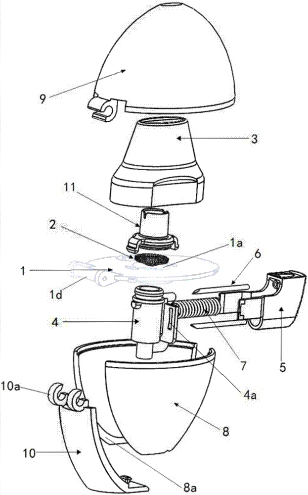
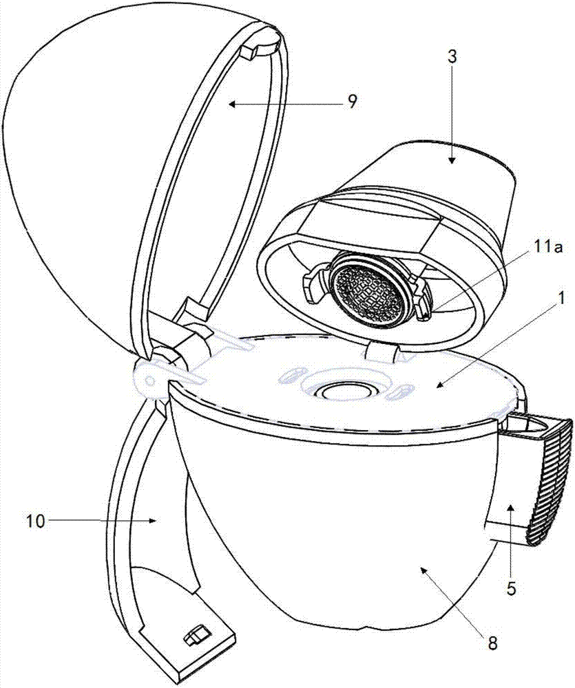
[0086] Figure 2 to Figure 7 A preferred embodiment of the dry powder inhaler of the present application is shown, which is the same as the traditional structure, and it also includes: a loading plate 1, a screen 2, a suction nozzle 3, a capsule chamber 4, a button 5, a spring 7, a lower Structural parts such as shell 8 and upper shell 9. in:

[0087] A through hole 1 a is formed on the supporting plate 1 .

[0088] The screen 2 is disposed at the through hole 1 a on the supporting plate 1 .

[0089] The suction nozzle 3 is disposed above the supporting plate 1 , and the suction nozzle 3 accommodates the screen 2 therein.

[0090] The capsule chamber 4 is detachably connected under the carrier plate 1, and the capsule chamber is also located at the above-mentioned through hole 1a. The capsule chamber 4 is made of transparent material.

[0091] The button 5 is connected with a pointed pin 6, and the pointed pin 6 can extend into the capsule chamber by pressing the button 5...

Embodiment 2

[0119] Figure 8 and Figure 9 It shows the second preferred embodiment of the dry powder inhaler of the present application, its structure is basically the same as that of the dry powder inhaler in Embodiment 1, the main difference between the two lies in the following aspects:

[0120] First, in this embodiment, the upper shell 9 is no longer an integral structure, but is composed of a split left half shell 901 and a right half shell 902, and the left half shell 901 and the right half shell 902 are pivotally connected respectively On the left side and the right side of the bearing plate 1, the two are split structures.

[0121] Secondly, in this embodiment, the lower case 8 is no longer provided with the notch 8a extending from the upper open edge of the lower case to the bottom of the lower case, and naturally the rotating window 10 with the structure of the first embodiment will not be provided. Instead, this structure is used:

[0122] A U-shaped slit 8c is provided on...

Embodiment 3

[0126] Figure 10 to Figure 18 It shows the third preferred embodiment of the dry powder inhaler of the present application. Its structure is basically the same as that of the dry powder inhaler in Embodiment 1. The main differences between the two lie in the following aspects:

[0127] First, the connection modes among the upper shell 9 , the carrying plate 1 , the suction nozzle 3 and the lower shell 8 are different.

[0128] In this embodiment, the bottom of the above-mentioned suction nozzle 3 is pivotally connected with the bearing plate 1 . Specifically, the pivotal connection of the two is as follows:

[0129] The side of the bearing plate 1 is integrally formed with two bearing plate lugs 1h distributed at intervals, and the inner side of the two bearing plate lugs 1h close to each other is integrally formed with a coaxially arranged cylindrical inner boss 1j. The outer sides of the bearing plate lugs 1h facing away from each other are integrally formed with coaxiall...


PUM


Abstract

The invention discloses a dry powder inhaler, which comprises a bearing plate, a suction nozzle, a capsule chamber, a button, a spring and a lower shell, wherein through holes are formed in the bearing plate in a going-through mode; the suction nozzle is connected to the upper side of the bearing plate and is arranged on the through holes; the capsule chamber is connected to the lower side of the bearing plate and is located on the through holes; tip pins, which are made from metal, are connected to the button, and the tip pins, through a pressing action of the button, can extend into the capsule chamber; the spring is clamped between the button and the capsule chamber, and by virtue of the spring, elasticity away from the direction of the capsule chamber is exerted; the upper side of the lower shell is of an opening structure; the bearing plate is connected to an opening of the upper side of the lower shell, and meanwhile, the capsule chamber is accommodated within the lower shell; the tip pins are fixedly connected to the button by virtue of a plastic tip pin seat; the tip pins and the tip pin seat are fixed in an injection-molding mode; and the tip pin seat and the button are fixed in a clamping mode. According to the dry powder inhaler, the tip pins, when used, are prevented from getting fallen or displaced easily; and moreover, the capsule chamber can be cleaned by a user more conveniently.

Description

technical field [0001] The present application relates to a dry powder inhaler, which is used for delivering powdered medicaments, especially powdered medicaments for treating respiratory diseases (such as asthma and chronic obstructive pulmonary disease). Background technique [0002] In the known field of powder medicine inhalers, there are various kinds of powder medicine inhalers. Existing powder drug inhalers can be divided into three main categories: [0003] Type 1: Reservoir-type powder pharmaceutical inhalers, which have a reservoir in which a certain dose of powder can be stored, and a metering part that can be separated from the reservoir at each actuation A certain dose of powder is dispensed, and then the separated powder is inhaled into the patient's body through the exhaust tube. Disadvantages of this type of powder inhaler: 1. The amount of powder delivered each time is unstable; 2. The sealing performance of this type of powder drug inhaler is poor, so the...

Claims


Application Information

Patent Timeline
Patent Type & Authority Applications(China)
IPC IPC(8): A61M15/00
CPCA61M15/00A61M15/0001A61M15/0021A61M15/0031A61M15/0035A61M2202/064A61M2210/1025A61M2202/0007
Inventor 任瑞贤王敏
Owner SUZHOU SINGMED MEDICAL DEVICE SCI & TECH LTD
Learn More