
High-gain direct-current voltage converter capable of lowering current stress of switching tube

A DC voltage and current stress technology, which is applied in the direction of converting DC power input to DC power output, adjusting electrical variables, and output power conversion devices, can solve excessive capacitance stress, large current stress of switch tubes and diodes, and inductive current Large and other problems, to achieve the effect of reducing current stress and improving power capacity

Inactive Publication Date: 2017-07-04
SOUTH CHINA UNIV OF TECH
View PDF4 Cites 4 Cited by
  • Summary
  • Abstract
  • Description
  • Claims
  • Application Information

AI Technical Summary

Problems solved by technology

However, the output characteristics of new energy sources often do not meet the power quality requirements of existing industrial systems, and require power conversion before they can be used
Although traditional Z-source converters and quasi-Z-source converters can obtain larger output voltages at low duty cycles, in the case of large load power, the traditional Z-source converters and quasi-Z source converters The stress of the capacitor is too large, and the current flowing through the inductor is very large, which increases the difficulty of the magnetic core and winding of the inductor, and the current stress of the switch tube and diode is large, which is not conducive to system heat dissipation, thus limiting the Z source converter and Application of quasi-Z source converter

Method used


Image

  • High-gain direct-current voltage converter capable of lowering current stress of switching tube
  • High-gain direct-current voltage converter capable of lowering current stress of switching tube
  • High-gain direct-current voltage converter capable of lowering current stress of switching tube

Examples


Embodiment Construction

[0010] The present invention will be further described below in conjunction with specific examples.

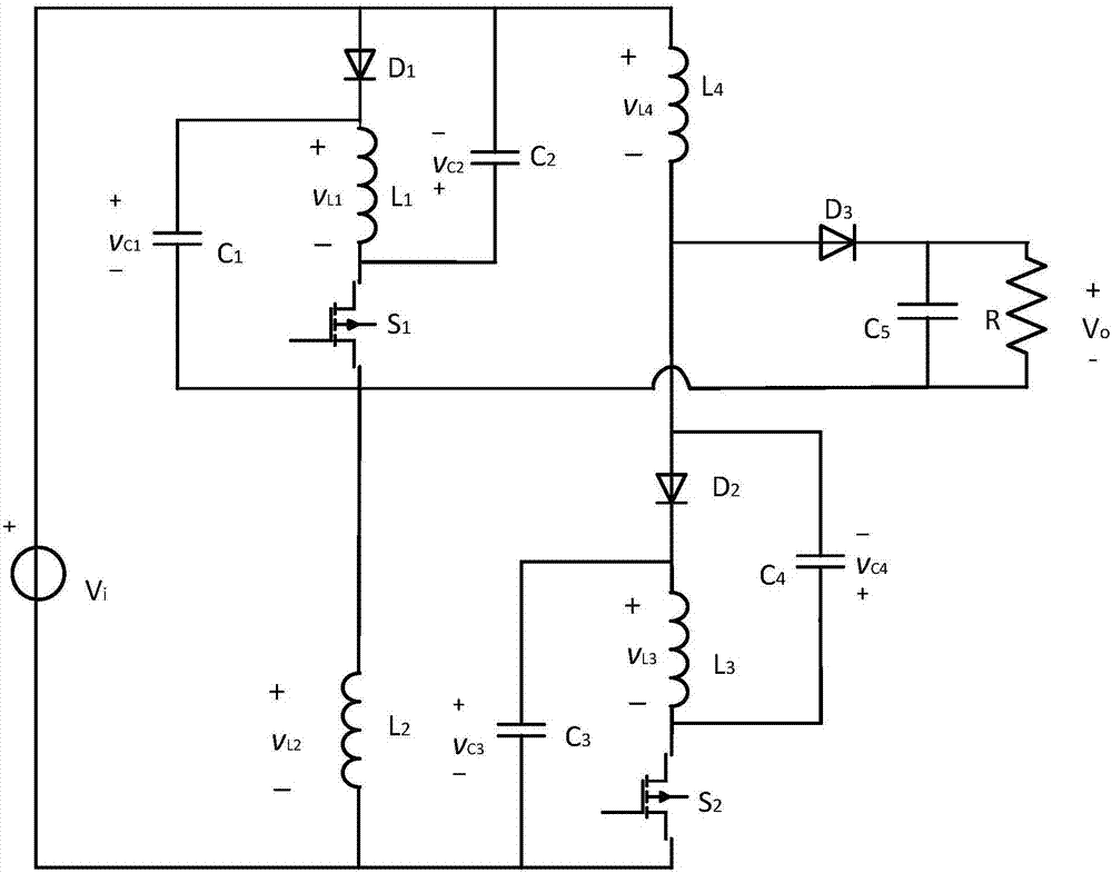
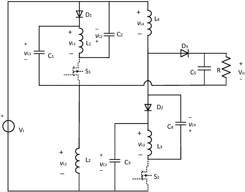
[0011] see figure 1 As shown, the high-gain DC voltage converter provided by this embodiment includes a voltage source V i , the first quasi-Z source module, the second quasi-Z source module, and the output module, the first quasi-Z source module is composed of the first capacitor C 1 , the second capacitance C 2 , the first inductance L 1 , the second inductance L 2 , the first switch tube S 1 and the first diode D 1 Composed of, the second quasi-Z source module consists of a third capacitor C 3 , the fourth capacitor C 4 , the third inductance L 3 , the fourth inductance L 4 , the second switch tube S 2 and the second diode D 2 Composed of, the output module consists of a third diode D 3 , the fifth capacitor C 5 and load R; the voltage source V i The anodes of the first diode D are respectively connected to the 1 The anode, the second capacitor C 2 The negat...


PUM


Abstract

The invention discloses a high-gain direct-current voltage converter capable of lowering current stress of a switching tube. The high-gain direct-current voltage converter comprises a voltage source, a first quasi-Z source module, a second quasi-Z source module and an output module, wherein the first quasi-Z source module consists of a first capacitor, a second capacitor, a first inductor, a second inductor, a first switching tube and a first diode; the second quasi-Z source module consists of a third capacitor, a fourth capacitor, a third inductor, a fourth inductor, a second switching tube and a second diode; and the output module consists of a third diode, a fifth capacitor and a load. By adoption of two groups of quasi-Z source modules, the current stress of the diodes and the switching tubes are obviously lowered; and meanwhile, the two groups of quasi-Z source modules have automatic current-sharing capability, so that power capacity is improved, and the circuit does not suffer from a starting impact problem.

Description

technical field [0001] The invention relates to the technical field of power electronic converters, in particular to a high-gain DC voltage converter based on a quasi-Z source bridge structure to reduce the current stress of a switch tube. Background technique [0002] Facing the increasingly serious energy crisis and environmental pollution problems, it has become a top priority to find new energy sources to replace the increasingly depleted fossil energy sources. However, the output characteristics of new energy often do not meet the power quality requirements of existing industrial systems, and require power conversion before they can be used. Although traditional Z-source converters and quasi-Z-source converters can obtain larger output voltages at low duty cycles, in the case of high load power, the traditional Z-source converters and quasi-Z source converters The stress of the capacitor is too large, and the current flowing through the inductor is very large, which in...

Claims


Application Information

Patent Timeline
Patent Type & Authority Applications(China)
IPC IPC(8): H02M3/158
CPCH02M3/158
Inventor 陈艳峰陈柱张波丘东元
Owner SOUTH CHINA UNIV OF TECH
Learn More