
Chemical reaction system and its filter unit and filter system

A technology of filtration unit and filtration system, applied in chemical instruments and methods, chemical/physical processes, filtration and separation, etc., can solve problems such as inability to reduce liquid viscosity, inability of filter media to withstand high temperature, filter clogging, etc.

Active Publication Date: 2019-08-20
CHNA ENERGY INVESTMENT CORP LTD +1
View PDF4 Cites 0 Cited by
  • Summary
  • Abstract
  • Description
  • Claims
  • Application Information

AI Technical Summary

Problems solved by technology

However, since the deformable filter medium filled in the filter chamber is mostly made of rubber, plastic and other materials, it is difficult to apply the filter to working conditions with severe temperature and pressure; moreover, when filtering viscous liquids, it is precisely Since the filter medium cannot withstand high temperature, it is impossible to reduce the viscosity of the liquid by increasing the operating temperature, which will cause the sticky particles that enter the pores of the filter medium to easily adhere to the surface of the filter medium, resulting in failure to wash out during backwashing, eventually causing The filter is clogged, and this will cause the device to stop, seriously affecting the long-term stable operation of the device

Method used


Image

  • Chemical reaction system and its filter unit and filter system
  • Chemical reaction system and its filter unit and filter system
  • Chemical reaction system and its filter unit and filter system

Examples


Embodiment Construction

[0038] Specific embodiments of the present invention will be described in detail below in conjunction with the accompanying drawings. It should be understood that the specific embodiments described here are only used to illustrate and explain the present invention, not to limit the present invention.

[0039] In the present invention, unless otherwise stated, the orientation words used should be properly understood in conjunction with the specific description in the specification or the directions shown in the drawings.

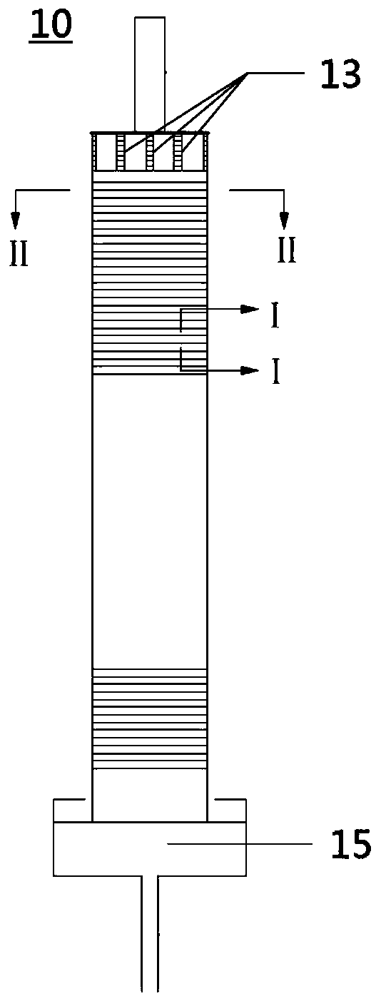
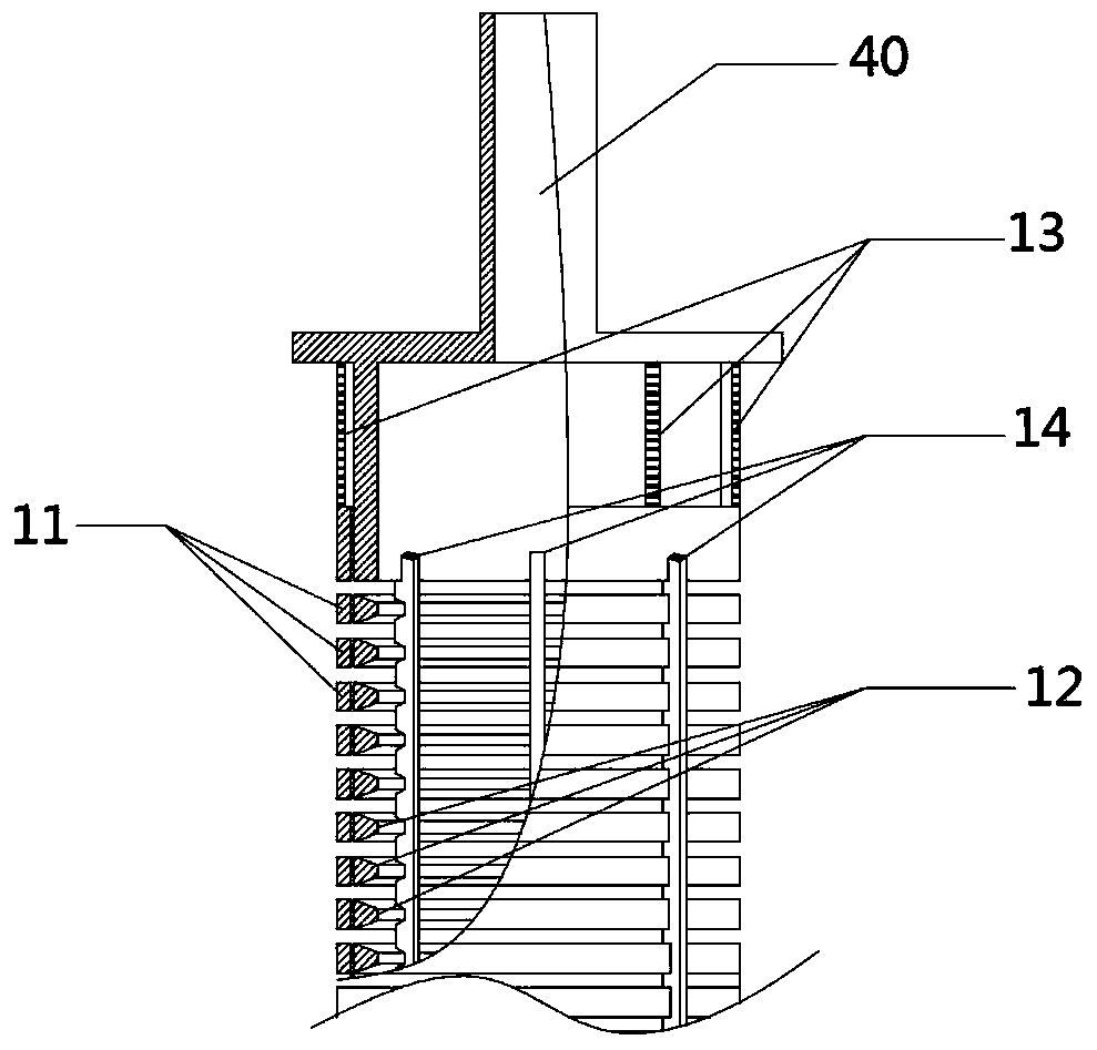
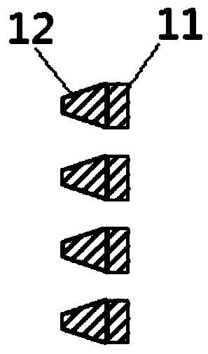
[0040]The present invention provides a filter unit, wherein the filter unit comprises two walls arranged at intervals oppositely, and a first filter layer 11 and a second filter layer 12 extending between the two walls along the length direction, the filter unit The surfaces of the first filter layer 11 and the second filter layer 12 are arranged adjacent to each other and are respectively provided with relatively communicating filter holes, wherein,

[0041...


PUM


Abstract

The invention relates to the field of raw material processing, and discloses a filtering unit, a filtering system and a chemical reaction system. The filtering unit comprises two walls which are oppositely arranged at intervals, a first filtering layer and a second filtering layer, wherein the first filtering layer and the second filtering layer extend between the two walls in the length direction, when the filtering unit performs filtering operation, a deformable device can deform to enable the size of the facing portion of each pair of filtering holes to be smaller than the size of the facing portion of each pair of the filtering holes when the filtering unit is in a natural state; when the filtering unit performs back flushing operation, the deformable device can deform to enable the size of the facing portion of each pair of the filtering holes to be larger than or equal to the size of the facing portion of each pair of the filtering holes when the filtering unit is in a natural state. According to the technical scheme, when the filtering unit performs the filtering operation, the size of the facing portion of each pair of the filtering holes can be reduced, and therefore the effect of fluid filtering is guaranteed, and when the filtering unit performs the back flushing operation, the size of the facing portion of each pair of the filtering holes is increased, so that the effect of back flushing is improved, and blockage of the filtering holes is effectively prevented.

Description

technical field [0001] The invention relates to the field of raw material processing, in particular to a filter unit, a filter system and a chemical reaction system. Background technique [0002] Filtration operation is an indispensable part of many chemical reactions, such as gas-liquid-solid three-phase slurry bed Fischer-Tropsch synthesis process, in which synthesis gas (CO+H 2 ) from the bottom of the slurry bed reactor into the slurry bed reactor where gas-liquid-solid three-phase coexistence occurs, and Fischer-Tropsch reaction occurs under the action of solid catalyst particles (mainly iron series) to generate liquid product Fischer-Tropsch wax (Fischer-Tropsch wax (Fischer-Tropsch wax) Wax is a methylene polymer, which is hydrocarbon-based synthesis gas or alkane synthesized from natural gas). During the reaction process, the generated Fischer-Tropsch wax needs to be continuously extracted from the slurry bed reactor through a filtration system to maintain the slurry...

Claims


Application Information

Patent Timeline
IPC IPC(8): B01D29/56B01D29/68B01J8/00
Inventor 张奉波门卓武卜亿峰张晓方李永龙翁力
Owner CHNA ENERGY INVESTMENT CORP LTD
Learn More