
Shielding connecting structure

A technology of shielding structure and connector, applied in the direction of connection, two-part connection device, protective grounding/shielding device of connection parts, etc., can solve the problems of inconvenient assembly, high labor cost, high parts cost and assembly cost, etc. Convenience, simple process and waterproof effect

Active Publication Date: 2017-06-30
YAZAKI CHINA INVESTMENT
View PDF7 Cites 15 Cited by
  • Summary
  • Abstract
  • Description
  • Claims
  • Application Information

AI Technical Summary

Problems solved by technology

[0005] However, there are many deficiencies in the shielding structure of the traditional high-voltage connector as mentioned above, for example: 1. The assembly is inconvenient, especially the various screw fastening processes are time-consuming and the labor cost is high; 2. The main terminal The waterproofing and shielding parts need to be waterproofed separately, which leads to the need to use more waterproof plugs, and the cost of parts and assembly is expensive; 3. Due to structural limitations, it is difficult to form a large compression rate on the circumference, so relying on waterproof plugs Self-shrinking to waterproof, can only achieve very weak waterproof ability

Method used


Image

  • Shielding connecting structure
  • Shielding connecting structure
  • Shielding connecting structure

Examples


Embodiment Construction

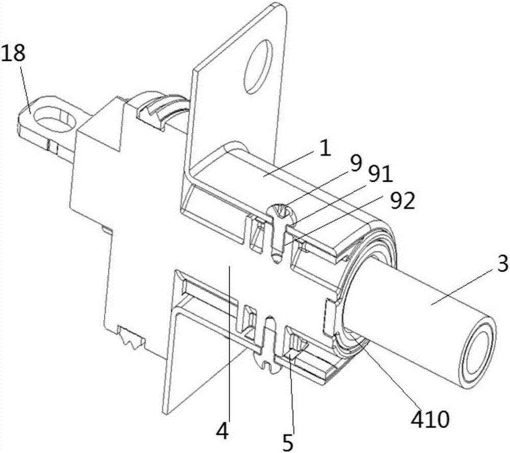
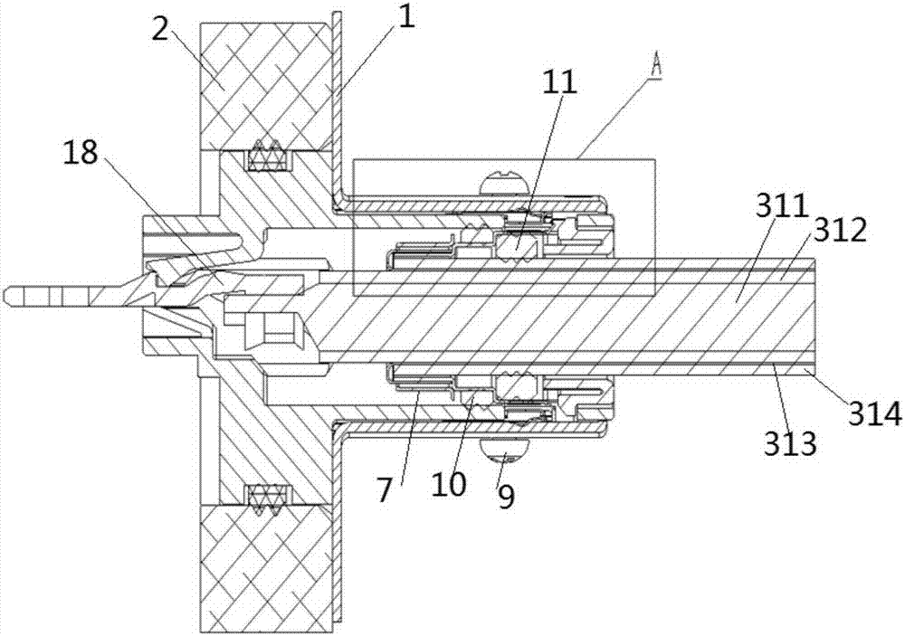
[0088] In the following, reference will be made to Figures 1 to 12 A shield connection structure according to an embodiment of the present invention will be described.

[0089] The shielding connection structure of the present invention is suitable for connecting shielded wires to connectors and realizing shielding conduction, and is also suitable for connecting unshielded wires to connectors and realizing shielding conduction. In this embodiment, the connector refers to a high-voltage connector for high voltage, which will be connected to the electrical housing, and of course it is also applicable to other types of connectors.

[0090] First, by referring to figure 1 -7 describes the condition of the shielding structure when shielding the wire.

[0091] like Figure 5 As shown, the shielded electric wire 3 in this embodiment is a coaxial cable, including: a conductor 311, for example, made by twisting a plurality of strands, or a single strand; an insulating layer made o...


PUM


Abstract

Provided is a shielding structure for a connector. The shielding structure comprises a cylindrical shielding shell, a cylindrical insulating jacket and a cylindrical first sealing element, wherein the jacket is inserted and installed into the shielding shell via an opening in one side of the shielding shell, and the jacket is provided with an electric wire insertion port for inserting an electric wire in one side; and the first sealing element is pressed into the jacket to realize water proofing. The shielding structure definitely realizes tight water proofing and shielding, is simple in structure, convenient to assemble and compact in size, and thus realizing miniaturization, light weight and low cost.

Description

technical field [0001] The present invention relates to a shielded connection structure, and more particularly, to a shielded connection structure for connecting a shielded wire or an unshielded wire with a connector and realizing shielded conduction. Background technique [0002] Traditionally, for connectors, especially high-voltage connectors, a split shell structure is usually adopted, in which shell a and shell b are buckled up and down and then fixed with screws, such as Figure 11 and 12 shown. The shielded connection structure 100 is configured to connect the above-mentioned split type high-voltage connector with the shielded electric wire 101 and make the connection part waterproof. The shielded electric wire 101 is a coaxial cable, and has a structure such that one or more inner conductors (core wires) are covered with a first insulating covering (inner insulator), and the outer conductor provided on the outer circumference of the inner insulator is covered with a...

Claims


Application Information

Patent Timeline
Patent Type & Authority Applications(China)
IPC IPC(8): H01R13/648H01R13/50H01R24/86H01R11/11
CPCH01R11/11H01R13/50H01R13/648H01R24/86
Inventor 曾艮富陈海峻池田智洋
Owner YAZAKI CHINA INVESTMENT
Learn More